Flexibility, Ondemand operation, Simplicity – ClimaCool UCH SHC onDEMAND Simultaneous Heating and Cooling Heat Recovery User Manual
Page 4: Dramatic energy savings, Compact, Ultimate efficiency, True redundancy, Source load cooling load heating
Load Hot
Loop
Load Cold
Loop
Flexibility
The 6 header design can be applied with
cooling towers, geothermal (ground and lake) loops,
or hybrid systems for true system flexibility. Cooling,
heating and source piping configuration is available
on same or opposite ends which allows for numerous
piping layouts. Bank sizes range from 30 to 1,000 tons
to ensure load demands are met efficiently.
onDEMAND Operation
Allows any module to
be indexed for heating or cooling regardless of its
position in the bank, providing optimum module/
compressor run time equalization.
Simplicity
6 header design simplifies installation,
design and controls. Simultaneously, the SHC satisfies
required heating and cooling demands without the
use of inter-module/external header isolation valves,
controls, associated logic, piping or wiring.
Dramatic Energy Savings
Eliminate the need
for separate heating and cooling systems thus saving
installation cost, overall operating cost, reducing
physical footprint while potentially lowering system
energy costs by more than 50% when compared to
traditional boiler/chiller systems.
Compact
No more need for bulky chiller systems
and large boiler room equipment. The SHC provides
the functionality of both in a minimal footprint. Patent
pending 6 header design eliminates the required space
between and external to the modules. This creates the
smallest system operating footprint when compared
to a typical simultaneous system and allows for same
end piping connections. Modular 6 pipe design allows
access through standard 36” doorways and onto
typical freight elevators.
Ultimate Efficiency
The CoolLogic Control
System provides advanced algorithms for maintaining
precise leaving chilled and hot water temperatures.
Integral motorized valves allow for variable pumping
on heating, cooling and source water loops. High
efficiency design offers cooling efficiencies up to 25
EER and heating efficiencies up to 5 COP.
True Redundancy
Separate module electrical
feeds provide true electrical redundancy. Integral
motorized isolation valves and dual independent/
refrigerant circuits per module provide true
mechanical redundancy.
Source
Loop
Load Hot
Loop
Load Cold
Loop
Produce heating, cooling and hot water from a single unit
• Simultaneous heating/cooling available from each module
• Provides hot water, as high as 135
o
F, utilizing R-410A refrigerant and 165
o
F utilizing R-134a refrigerant
• Built in modulating head pressure control
Use free heat to reduce energy consumption
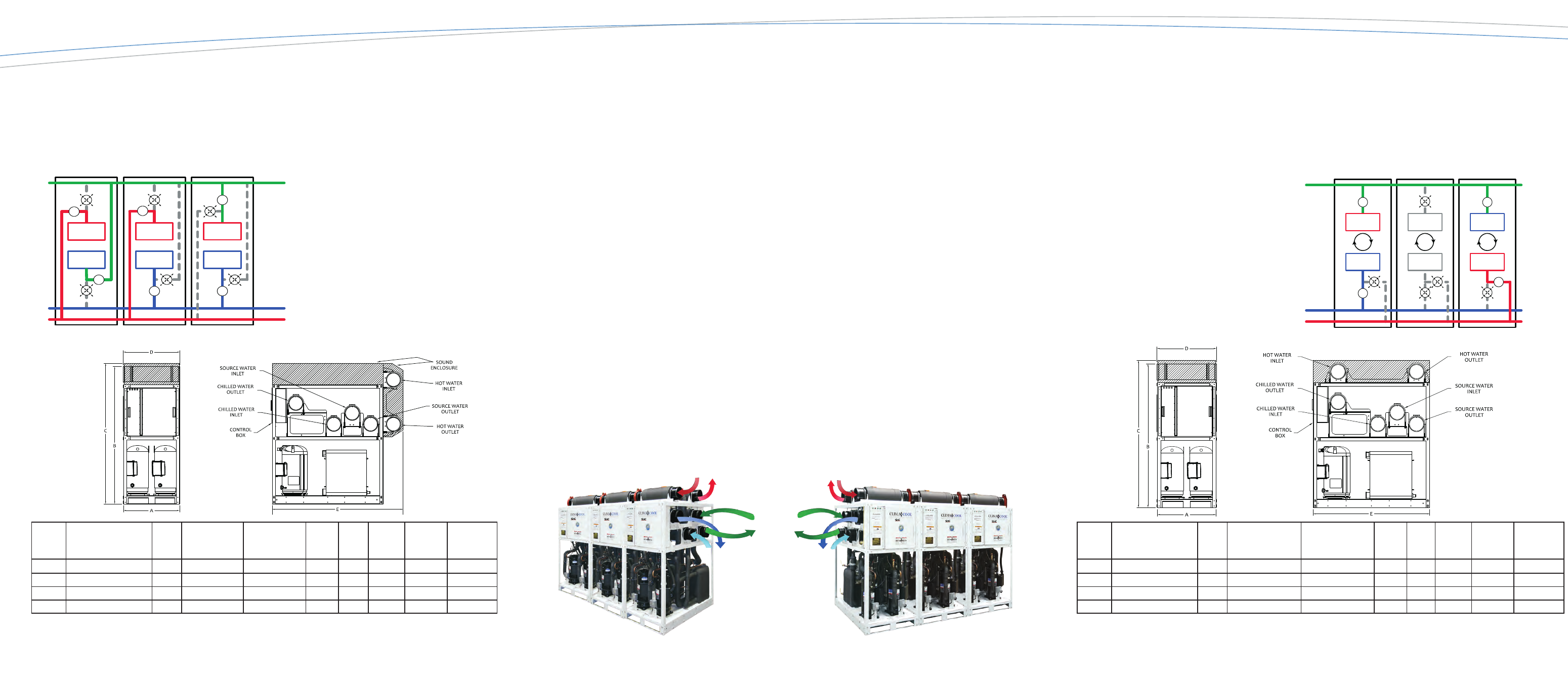
Heat Recovery Model
Figure shows a bank of three modules:
Module 1 in Heating
Module 2 in Heating and Cooling
Module 3 in Cooling
MODEL
UCH
VOLTAGE
A
UNIT
WIDTH
(in.)
B
HEIGHT WITHOUT
SOUND ENCLOSURE
(in.)
C
HEIGHT WITH
SOUND ENCLOSURE
(in.)
D
HEADER
WIDTH
(in.)
E
UNIT
DEPTH
(in.)
UNIT
WEIGHT
1
(lb.)
OPERATING
WEIGHT
2
(lb.)
HEADER
CONNECTION
SIZE
3
(in.)
030
208/230/460/575/3/60
34
78 7/8
80
34 1/4
67 3/4
1530
1850
6
050
208/230/460/575/3/60
34
78 7/8
80
34 1/4
67 3/4
2150
2460
6
070
208/230/460/575/3/60
34
78 7/8
80
34 1/4
67 3/4
2400
2710
6
085
208/230/460/575/3/60
34
82 7/8
84 7/8
34 1/4
79 1/4
2850
3350
8
Notes:
1. Unit shipping weight includes refrigerant charge, compressor oil and packaging.
2. Operational weight includes refrigerant charge, compressor oil and water.
3. The model UCH085 cannot be directly coupled with model UCH030, 050 or 070 due to differences in header and frame size.
V
V
V
V
V
V
V
V
V
V
V
V
Module 1
Heating
Module 2
Heating and Cooling
Module 3
Cooling
Source
Load Cooling
Load Heating
*Simplified single line water circuit shown; V=motorized isolation and control valve
Index any module for heating or cooling at ANY time
Heat Pump Model
• Lower compression ratios due to operation at neutral source temperatures
• Provides hot water, as high as 135
o
F, utilizing R-410A refrigerant and 165
o
F utilizing R-134a refrigerant
• Built in modulating head pressure control
• No mixing of source and load liquids (water/glycol) solutions
Figure shows a bank of three modules:
Module 1 in Cooling
Module 2 in Standby
Module 3 in Heating
V
V
V
V
V
V
V
V
V
Module 1
Cooling
Module 2
Standby
Module 3
Heating
Source
Load Cooling
Load Heating
MODEL
UCH
VOLTAGE
A
UNIT
WIDTH
(in.)
B
HEIGHT WITHOUT
SOUND ENCLOSURE
(in.)
C
HEIGHT WITH
SOUND ENCLOSURE
(in.)
D
HEADER
WIDTH
(in.)
E
UNIT
DEPTH
(in.)
UNIT
WEIGHT
1
(lb.)
OPERATING
WEIGHT
2
(lb.)
HEADER
CONNECTION
SIZE
3
(in.)
030
208/230/460/575/3/60
34
76 7/8
78
34 1/4
55 1/2
1530
1850
6
050
208/230/460/575/3/60
34
76 7/8
78
34 1/4
55 1/2
2150
2460
6
070
208/230/460/575/3/60
34
76 7/8
78
34 1/4
55 1/2
2400
2710
6
085
208/230/460/575/3/60
34
83 7/8
84 7/8
34 1/4
67
2850
3350
8
Notes:
1. Unit shipping weight includes refrigerant charge, compressor oil and packaging.
2. Operational weight includes refrigerant charge, compressor oil and water.
3. The model UCH085 cannot be directly coupled with model UCH030, 050 or 070 due to differences in header and frame size.
*Simplified single line water circuit shown; V=motorized isolation and control valve
on
DEMAND
®
SIMULTANEOUS HEATING AND COOLING
on
DEMAND
®
SIMULTANEOUS HEATING AND COOLING
on
DEMAND
®
SIMULTANEOUS HEATING AND COOLING
on
DEMAND
®
SIMULTANEOUS HEATING AND COOLING
on
DEMAND
®
SIMULTANEOUS HEATING AND COOLING
on
DEMAND
®
SIMULTANEOUS HEATING AND COOLING