Adjustments – CHIEF KWK-110 User Manual
Page 7
Installation Instructions
KWK-110
7
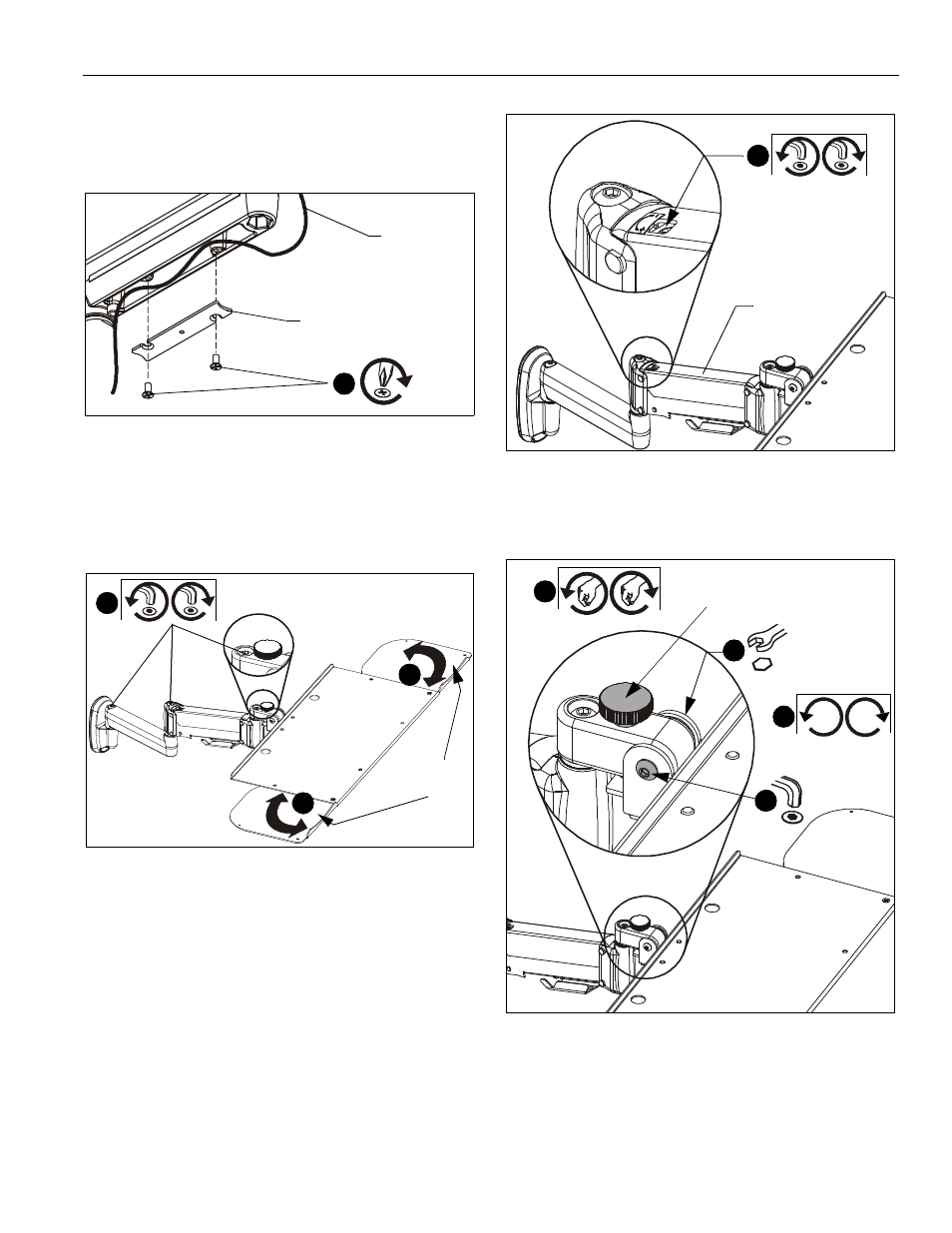
5.
Carefully insert cables into cavity located in lower portion of
mount arm. (See Figure 8)
6.
Install cable management cover (B) using two #8-32 x 3/8"
Phillips flat head screws (J). (See Figure 8)
Figure 8
ADJUSTMENTS
Swing Arm Pivot/Swing Adjustment
1.
Slightly loosen or tighten the adjustment screw(s) as
necessary, using the 3/16" hex key (K). (See Figure 9)
Figure 9
Mouse Tray Adjustment
2.
Mouse trays slide open and closed on both sides of the tray
for use by both right- and left-handed users. (See Figure 9)
Height Adjustment
3.
Slightly loosen or tighten the height adjustment screw as
necessary, using the 5/32" hex key (L). (See Figure 10)
•
If keyboard tray lowers on its own, rotate
adjustment screw counterclockwise (towards
the "+" symbol).
•
If keyboard tray rises on its own, rotate
adjustment screw clockwise (towards the "-"
symbol).
NOTE:
It may be necessary to raise or lower the height
adjustable arm to expose the adjustment screw.
Figure 10
4.
Adjust tray tension using a 7/16" wrench and a 5/32" (L) hex
key. (See Figure 11)
Figure 11
5.
Adjust the tilt angle adjustment knob as necessary to set tilt
angle of keyboard tray. (See Figure 11)
(J) x 2
(B)
Cable path
(typical)
6
Pivot/Swing adjustment screws
Adjustable
mouse trays
1
2
2
Height adjustment
screw
Height
adjustable
arm
3
4
4
5
4
Tilt angle
adjustment knob