CHIEF FWDSK110 User Manual
Page 7
Installation Instructions
FWDSK110
7
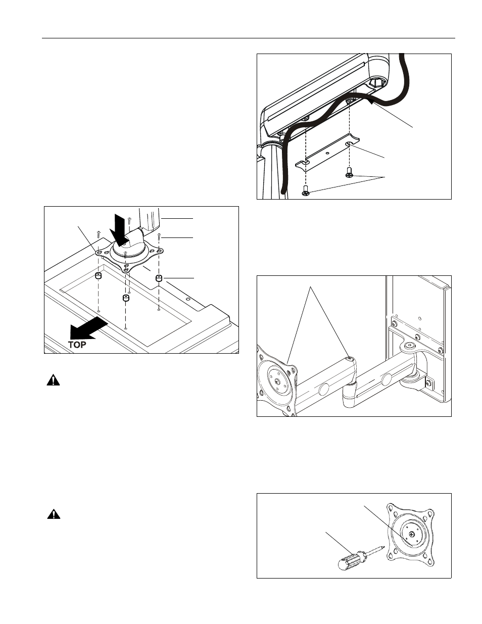
2. Carefully place display face down on protective
surface.
3. Determine depth of recessed mounting holes relative
to back surface of display (against which Centris head
will contact). (See Figure 8)
4. Select proper length spacer and screw.
(See Figure 8)
NOTE:
All spacers used should be the same length. If
the recess depths result in multiple spacer
lengths, then select the longer spacer.
5. Place the four selected spacers over each of the
mount holes on the back of the display.
6. Pick up and orient the mount (A) so that the mounting
holes in the Centris bracket are aligned with the holes
in the spacers; rotate the bracket as required. (See
Figure 8)
Figure 8
WARNING:
IMPROPER INSTALLATION CAN LEAD TO
EQUIPMENT FALLING CAUSING SERIOUS PERSONAL
INJURY OR DAMAGE TO EQUIPMENT! Using screws of
improper size may damage your display! Proper screws will
easily and completely thread into display mounting holes.
7. Using Phillips screwdriver, install four screws (D or H)
through the mounting holes in Centris bracket,
through the spacers (F or G), and into the display.
(See Figure 8)
8. Tighten all four screws. Do not overtighten!
CABLE MANAGEMENT
1.
Attach all cables to display.
CAUTION:
Ensure that adequate cable slack exists for
movement of display, and that cables will not be pinched by
installation of cover (C) or screws (E).
2. Carefully insert cables in cavity located in lower
portion of mount arm (See Figure 9).
3. Using Phillips screwdriver, install cover (10) with two
screws (20). (See Figure 9)
Figure 9:
ADJUSTMENTS
Swing Arm
PIVOT / SWING
1.
Using 3/16" hex key, slightly loosen or tighten the
adjustment screw(s) as necessary (See Figure 10).
Figure 10
Centris Head
1.
If previously attached, disconnect cables from display, then
remove display.
2. Using Phillips screwdriver, slightly loosen or tighten
the adjustment screw as necessary (See Figure 11).
Figure 11
(A) x 1
(D or H) x4
(F or G) x 4
Centris Bracket
(E) x 4
Cable Path
(typical)
(C) x 2
Adjustment Screws
Adjustment Screw
Phillips Screwdriver