Tools required for installation parts – CHIEF WM2 Series User Manual
Page 6
Installation Instructions
6
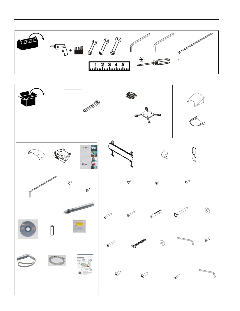
TOOLS REQUIRED FOR INSTALLATION
PARTS
1/2" (12.7mm)
#2
7/32" (5.6mm)
3/8" (9.5mm)
3/16"
(included)
5/32"
(included)
(security)
1/2" (12.7mm)
5/32" - 6" long
(included)
(security)
D (2)
[wall bracket
E (2)
1/4-20 x 5/8"
H (4)
1/4-20 x 1-1/2"
K (4)
N (4)
1/4-20 x 1-3/4"
P (4)
1/4-20
B (1)
[wall bracket]
C (2)
[wall bracket
F (10)
#8-32 x 1/2"
G (4)
1/4-20 x 3/8"
J (4)
#10-24 x 1-3/8"
S (4)
#10-24 x 3/8"
W (1)
5/32"
(security)
top cap]
bottom cap]
Q (4)
1/4"
R (1)
3/16"
[concrete
anchor]
X (1)
[Cover-top]
Y (1)
[Interactive cover]
AC (1)
[Interactive
software]
AD (1)
[AAA battery]
AH (1)
[Interactive
A (1)
[Short throw wall mount]
AE (1)
[Stylus]
AF (4)
[Stylus
replacement
tips]
AG (1)
[Stylus
wrist strap
kit]
USB cable]
AA (4)
8-32 x 3/8"
(security)
AB (4)
8-32 x 3/8"
Z (1)
5/32"
(security)
(WM2XXSI/WM2XXAUSI Interactive Models Only)
(WM2XXS/WM2XXAUS
All Models
L (4)
5/16 x 2-1/2"
M (6)
T (2)
1/4-20 x 1/2"
(security)
U (4)
1/4-20 x 3/4"
(security)
V (10)
#8-32 x 1/2"
(security)
AJ (1)
[Upper cover]
AK (1)
[Lower cover]
Models Only)
All Models
5/16"
Quick Start
Guide
Interactive
Software
Guide
(WM2XXAUS/AUSI Models Only)
(WM220 shown as example only)
X (1)
[RSM]
Y (1)
[SSMU interface bracket]