Repair parts list and diagrams – J&M 1050-18S User Manual
Page 15
15
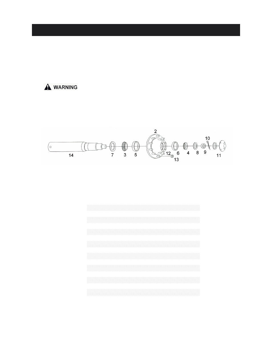
HUB AND SPINDLE ASSEMBLY
REPAIR PARTS LIST AND DIAGRAMS
When performing maintenance work, wear sturdy, rough-soled work shoes and protective equip-
ment for eyes, hair, hands, hearing and head. Follow Operator’s Manual instructions to ensure
safe and proper maintenance and repair.
Your local, authorized dealer can supply genuine replacement parts. Substitute parts may not
meet original equipment specifications and may be dangerous.
BE CERTAIN THAT ALL POWER IS SHUT OFF BEFORE PERFORMING ANY MAINTENANCE
OR REPAIR WORK.
#
Part #
Description
1
31x32-10
Wheel Rim, 10 hole 31x32 (3 pc)
OR-3132
Rubber O-Ring Seal
31x32-1P-10
Wheel Rim, 10 hole 31x32 (1 pc)
32x36-10
Wheel Rim, 10 hole 32x36
2
H25000
Hub w/Studs and Nuts
3
71455
Large Bearing
4
663
Small Bearing
5
71750
Large Race
6
653
Small Race
7
CR55179
Seal
8
EM-25M
Spindle Washer
9
SF-2512
Slotted Spindle Nut
10
3754
Cotter Pin
11
D-25000
Dust Cap w/Gasket
12
22MM-90
Wheel Stud, 22 MM x 90 MM
13
22MM-N
Wheel Nut, 22 MM
14
628
Spindle, 6" diameter x 28"
15
HSA-1075
Hub and Spindle Assembly
16
18HBLN
1" x 8" Hex Bolt w/Lock Nut