Scooter part diagrams, Diagram 2: the handlebars and controls – Daymak Boomerbuggy Covered User Manual
Page 5
5
1
2
3
5
4
6
7
12
10
11
9
8
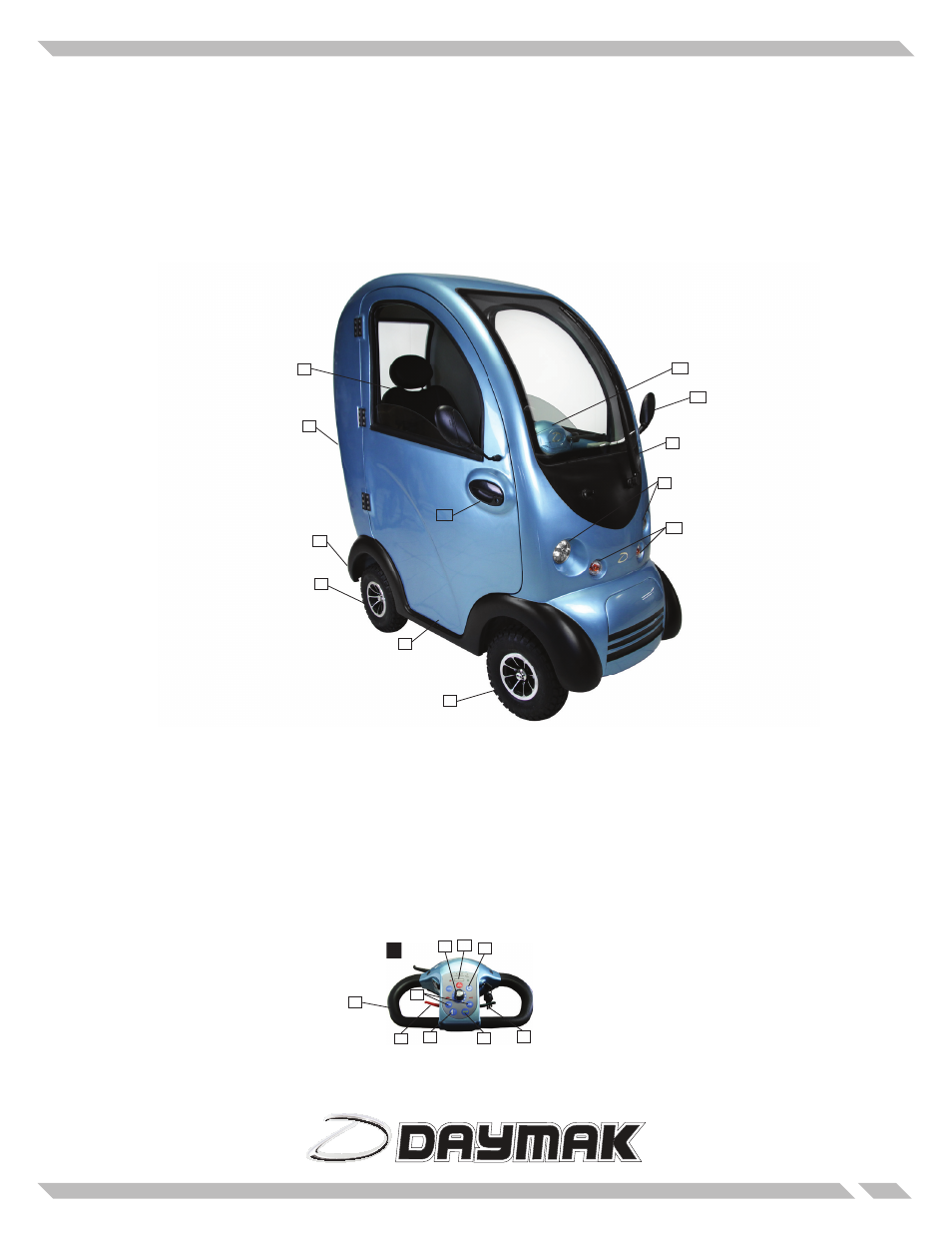
Scooter Part Diagrams
Diagram 1: The Boomerbuggy Covered Electric Scooter
This diagram illustrates the various parts of your scooter. Please note that many of these parts are not us-
er-serviceable and should be repaired only by trained professionals. This is especially true of the electrical
systems and the mechanical components.
Diagram 2: The Handlebars and Controls
This diagram illustrates the various parts of your scooter. Please note that many of these parts are not us-
er-serviceable and should be repaired only by trained professionals. This is especially true of the electrical
systems and the mechanical components.
1. Seat
2. Rear Lights / Indicators
3. Anti-tip wheels
4. Rear Wheel(s)
5. Foot Rest
6. Front Wheel(s)
7. Headlights
8. Turn Signals
9. Windshield Wiper
10. Control Panel
11. Mirrors
12. Door handle
1. Accelarator
2. Reverse
3. Steering wheel
4. Speed control
5. Turn signals
6. Headlight switch
7. Horn
8. Battery indicator
9. FreeWheel switch
5
2
3
4
6
8
7
1
9