Bicycle part diagrams, Diagram 1: the utility electric bicycle, Diagram 2: the handlebars and controls – Daymak Utility Deluxe User Manual
Page 5
5
1
2
3
5
4
6
8
7
10
9
11
17
18
13
14
15
16
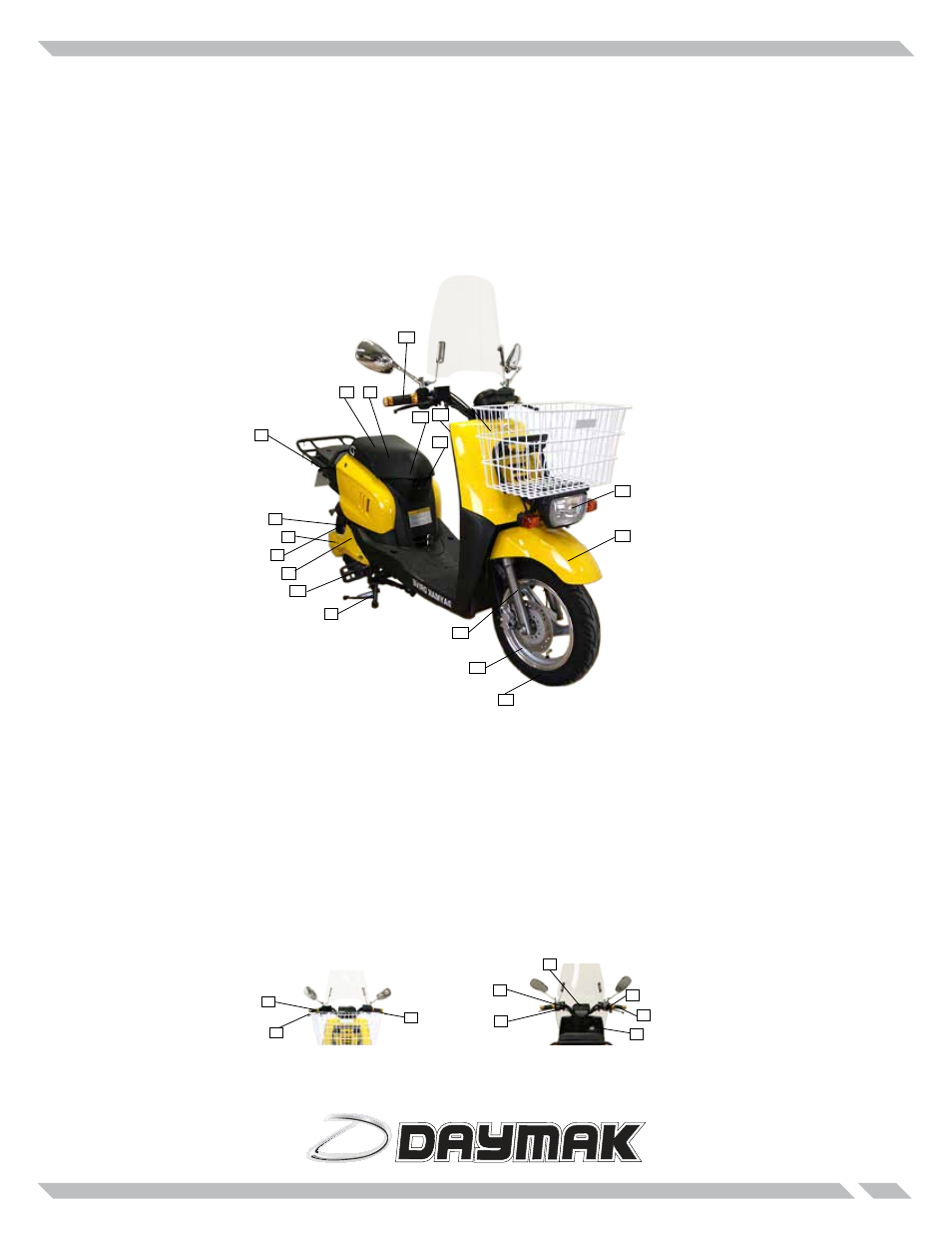
Bicycle Part Diagrams
Diagram 1: The Utility Electric Bicycle
This diagram illustrates the various parts of your bicycle. Please note that many of these parts are not us-
er-serviceable and should be repaired only by trained professionals. This is especially true of the electrical
systems and the mechanical components.
Diagram 2: The Handlebars and Controls
This diagram illustrates the various parts of your bicycle. Please note that many of these parts are not us-
er-serviceable and should be repaired only by trained professionals. This is especially true of the electrical
systems and the mechanical components.
1. Seat
2. Taillight
3. Rear Mudguard/Fairing
4. Rear Wheel
5. Rear Shock Absorber
6. Hub Motor
7. Controller (inside)
8. Kickstand
9. Battery (inside)
10. Battery charger slot
11. Front Fork
12. Wheel Rims
13. Tire
14. Front Mud Guard
15. Headlight
16. On / Off key switch
17. Handlebars
18. Pedals
1. Accelarator
2. Front brake controller
3. Rear brake controller
4. Speedometer
5. Turn signals
6. Headlight/Tail light switch
7. Horn
8. Ignition
9. Speed control
1
2
3
4
5
7
12
6
8
9