Power supply alarm mute connector definition, Power supply alarm signal connector definition – Chenbro RM51424 LED Board(80H033215-005 Rev.A0~A2), For 3Gbps mini-SAS Backplane - Manual User Manual
Page 7
LED Board 80H033215-005 ver. A0~A2
User’s Manual
15Fl., No.150, Jian Yi Road, Chung Ho City, Taipei Hsien, Taiwan R.O.C.,
Tel: +886 2 82265500 Fax: +886 2 82265392 Email: [email protected]
7
www
.chenbr
o.com
Function Switch Pin Definition
SW 1
SW 2
SW 3
SW 4
ON
Fan1~5 Monitoring
Enable
System Alarm
Temperature is 65°C
Fan Monitoring
Enable
HDD Sequential
Spin up Disable
OFF
Fan1~4 Monitoring
Enable
System Alarm
Temperature is 55°C
Fan Monitoring
Disable
HDD Sequential
Spin up Enable
SW 5
SW 6
4 HDDs
OFF
OFF
8 HDDs
ON
OFF
12 HDDs
OFF
ON
16 HDDs
ON
ON
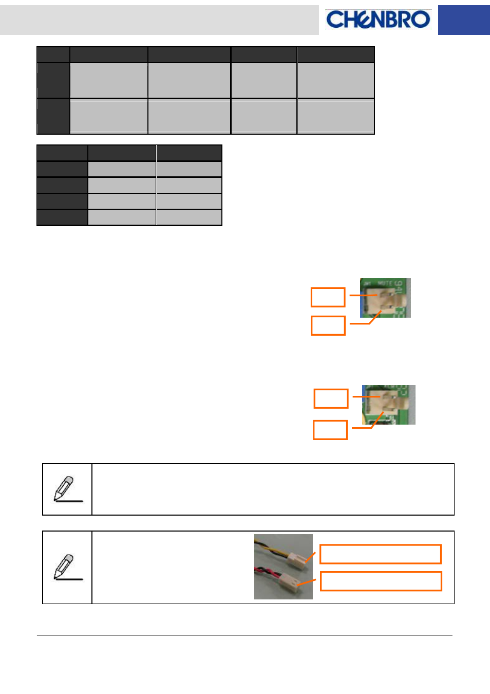
Power Supply Alarm Mute Connector Definition
Pin 1: Ground
Pin 2: Alarm mute signal output to PSU (Active low)
Power Supply Alarm Signal Connector Definition
Pin 1: Ground
Pin 2: PSU fail signal (TTL) input from PSU (Active low)
Only redundant PSU come with the failure alarm and alarm mute reset control via signal
connector. Make sure the redundant PSU that user applied come with the connectors
above.
This picture shows the standard
“2510 2-pin” type PSU alarm signal
connectors which fitting Chenbro
LED board.
Pin 1
Pin 2
Pin 1
Pin 2
Mute (Yellow & Black wire)
TTL (Red & Black wire)
- NR40700 6Gb/s 24-port 3.5 mini-SAS expander backplane(80H10024001A0) - Manual (17 pages)
- RM13108 LED Board(80H033131-001), Features and Jumper Settings - Manual (8 pages)
- RM13108 6Gb/s 8-port 2.5 SATA/SAS Backplane (80H10313107A0), Rev. A0 - Manual (10 pages)
- RM13108 3Gb/s 8-port 2.5 SATA/SAS Backplane (80H103131-003) - Manual (7 pages)
- RM13604 6Gb/s 4-port 3.5 SATA/SAS Backplane (80H10313601A0), Rev. A0 - Manual (11 pages)
- RM24200 LED Board(80H03324101A0), Features and Jumper Settings - Manual (8 pages)
- RM21600 LED Board (80H033216-004), Features and Jumper Settings - Manual (8 pages)
- RM21706 6Gb/s 6-port 3.5 mini-SAS Backplane(80H10321711A0), Rev.A0 - Manual (12 pages)
- RM21706 3Gb/s 6-port 3.5 mini-SAS Backplane(80H10321709A0) - Manual (10 pages)
- RM21706 3Gb/s 6-port 3.5 SATA/SAS Backplane(80H103217-004) - Manual (6 pages)
- RM41416 6Gb/s 4-port 3.5 mini-SAS Backplane(80H10321516A1) Rev. A1 - Manual (25 pages)
- RM235 Series 6Gb/s 8-port 2.5 mini-SAS Backplane (80H10323406A0), Rev. A0 - Manual (11 pages)
- RM235 Series 6Gb/s 12-port 3.5 mini-SAS Expander Backplane(80H10323501A0), Rev.A0 - Manual (14 pages)
- RM235 Series 6Gb/s 24-port 2.5 mini-SAS expander backplane (80H10341802A0, 80H10341803A0, 80H17341801A0) - Manual (19 pages)
- RM23608 6Gb/s 8-port 3.5 mini-SAS Backplane(80H10323604A1), Rev. A1 - Manual (12 pages)
- RM23608 6Gb/s 8-port 3.5 SATASAS Backplane (80H10323601A1), Rev. A1 - Manual (12 pages)
- RM23612 6Gb/s 12-port 3.5 mini-SAS Backplane (80H10323602A1), Rev. A1 - Manual (13 pages)
- RM31408 6Gb/s 4-port 3.5 SATA/SAS Backplane(80H10331405A0) - Manual (11 pages)
- RM31408 6Gb/s 4-port 3.5 mini-SAS Backplane(80H10331404A0) - Manual (12 pages)
- RM31408 3Gb/s 4-port 3.5 mini-SAS Backplane(80H102209-013) - Manual (12 pages)
- SR107 Series 3Gb/s 4-port SATA/SAS Backplane(80H102209-010) Rev. B0, for 4-Bay 3.5 Hot-swap HDD Cage - Manual (10 pages)
- RM31408 3Gb/s 4-port 3.5 SATA/SAS Backplane(80H103314-002), Rev. A1 - Manual (9 pages)
- RM31616 6Gb/s 16-port 3.5 mini-SAS Expander Backplane(80H10331605A0) - Manual (8 pages)
- RM31616 6Gb/s 16-port 3.5 mini-SAS Backplane(80H10331604A0) - Manual (12 pages)
- RM31616 3Gb/s 16-port 3.5 mini-SAS Backplane(80H103316-001), Rev. A2/B0 - Manual (12 pages)
- RM41416 3Gb/s 4-port 3.5 mini-SAS Backplane(80H103215-013) Rev. A1 - Manual (21 pages)
- RM41416 3Gb/s 4-port 3.5 mini-SAS Backplane(80H103215-013) Rev. A0 - Manual (20 pages)
- RM417 Series 6Gb/s 24-port 3.5 Expander Backplane(80H10341801A0), For 24-bay 3.5 Hot-swap HDD Cage - Manual (18 pages)
- RM51424 LED Board(80H033215-003 Rev. 1.1~1.2), For 3Gbps SATA Backplane - Manual (11 pages)
- RM51424 LED Board(80H033215-005 Rev. A3) , For 3Gbps/6Gbps mini-SAS Backplane - Manual (10 pages)
- RM51424 3Gb/s 4-port 3.5 mini-SAS Backplane(80H10321513C0) Rev. C0 - Manual (21 pages)
- RM51424 3Gb/s 4-port 3.5 mini-SAS Backplane(80H103215-013) Rev. B0 - Manual (21 pages)
- RM51424 3Gb/s 4-port 3.5 mini-SAS Backplane(80H103215-013) Rev. A2~A3.1 - Manual (21 pages)
- SR107 Series 3Gb/s 4-port mini-SAS Backplane(80H102209-013), for 4-Bay 3.5 Hot-swap HDD Cage - Manual (12 pages)
- SR107 Series 3Gb/s 6-port mini-SAS Backplane(80H102209-014), for 6-Bay 2.5 Hot-swap HDD Cage - Manual (13 pages)
- SR107 Series 6Gb/s 4-port mini-SAS Backplane(80H10220918A0), for 4-Bay 3.5 Hot-swap HDD Cage - Manual (12 pages)
- SR107 Series 6Gb/s 6-port mini-SAS Backplane(80H10220920A0), for 6-Bay 2.5 Hot-swap HDD Cage - Manual (11 pages)
- SR107 Series 6Gb/s 4-port SATA/SAS Backplane(80H10220919A0), for 4-Bay 3.5 Hot-swap HDD Cage - Manual (11 pages)
- SR209 Series 6Gb/s 4-port 3.5 SATA/SAS Backplane(80H10220919A0), Rev A0 - Manual (11 pages)
- ES34169 - Installation (17 pages)
- SR105 Series - Installation (36 pages)
- SR112 Series 6Gb/s 4-port mini-SAS Backplane(80H10211203A0), for 4-Bay 3.5 Hot-swap Kit - Manual (11 pages)
- SR112 Series 6Gb/s 4-port SATA/SAS Backplane(80H10211202A0), for 4-Bay 3.5 Hot-swap Kit - Manual (11 pages)
- SR301 Series 6Gb/s 4-port 3.5 SAS/SATA Backplane(80H10230101A0), Rev. A0 - Manual (11 pages)