Led board layout, Backplane connectors, View – Chenbro RM13108 LED Board(80H033131-001), Features and Jumper Settings - Manual User Manual
Page 6
LED Board 80H033131-001
User’s Manual
15Fl., No.150, Jian Yi Road, Chung Ho City, Taipei Hsien, Taiwan R.O.C.,
Tel: +886 2 82265500 Fax: +886 2 82265392 Email: [email protected]
6
w
w
w
.
c
h
e
n
b
r
o
.
c
o
m
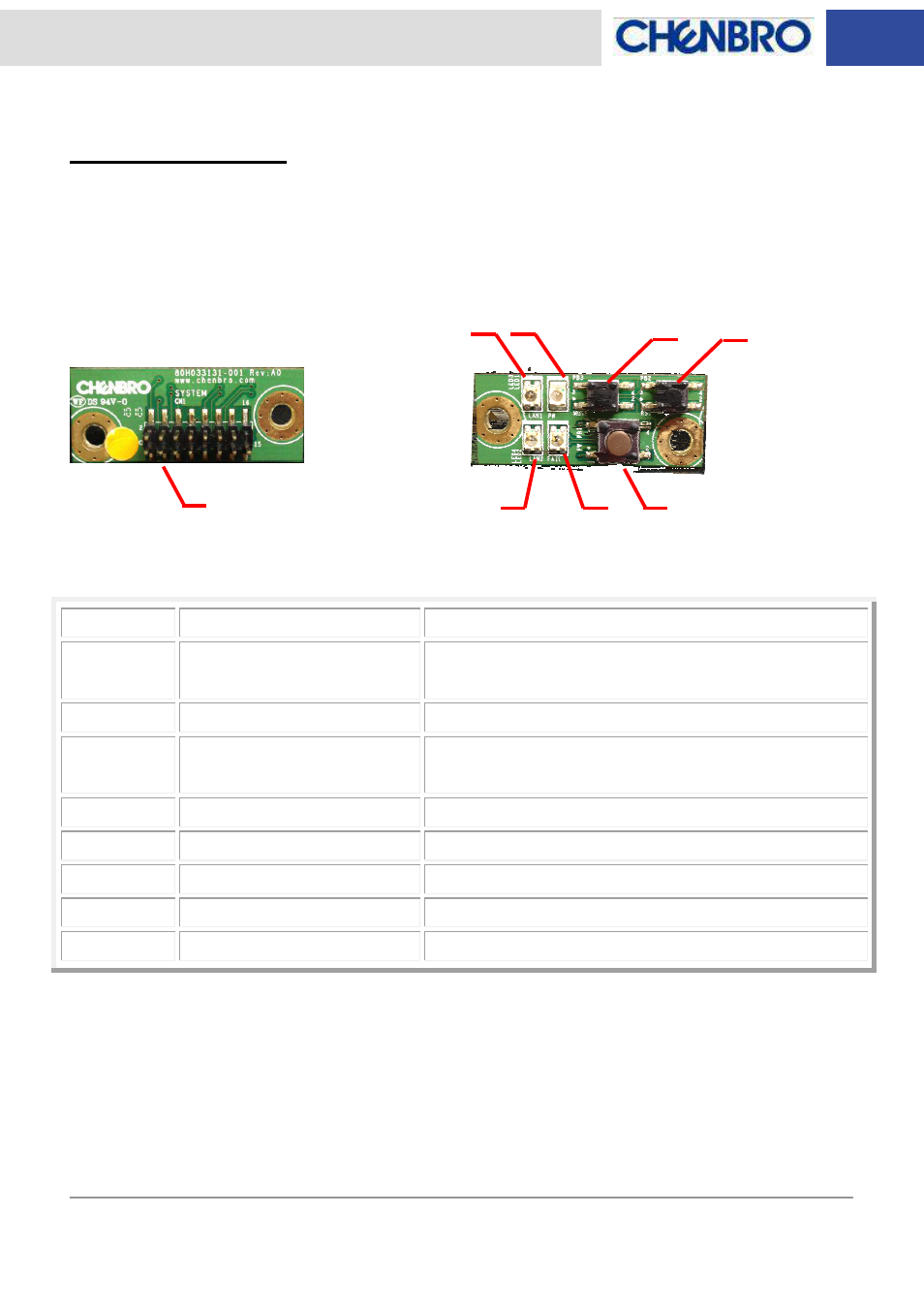
LED Board Layout
Backplane Connectors
Components
Description
Function
CN1
15 pin header
Connecting to M/B (Power SW, Reset SW, GND, Power
LED, LAN 1 & LAN 2) and BP (Fail & Mute)
LED1
Power LED
Blue indicator during the power on stage
LED2
Fail LED
Red indicator during the fail (For BP fan, BP temperature
& RPSU power signal indication)
LED3
LAN 1 LED
Green indicator during the network activity
LED4
LAN 2 LED
Green indicator during the network activity
PB1
Power Switch
Push button for system power on
PB2
Reset Switch
Push button for system reset
PB3
Mute Switch
Push button for alarm mute
Rear
View
Front View
LED1
PB2
PB3
CN1
PB1
LED3
LED4
LED2
- NR40700 6Gb/s 24-port 3.5 mini-SAS expander backplane(80H10024001A0) - Manual (17 pages)
- RM13108 6Gb/s 8-port 2.5 SATA/SAS Backplane (80H10313107A0), Rev. A0 - Manual (10 pages)
- RM13108 3Gb/s 8-port 2.5 SATA/SAS Backplane (80H103131-003) - Manual (7 pages)
- RM13604 6Gb/s 4-port 3.5 SATA/SAS Backplane (80H10313601A0), Rev. A0 - Manual (11 pages)
- RM24200 LED Board(80H03324101A0), Features and Jumper Settings - Manual (8 pages)
- RM21600 LED Board (80H033216-004), Features and Jumper Settings - Manual (8 pages)
- RM21706 6Gb/s 6-port 3.5 mini-SAS Backplane(80H10321711A0), Rev.A0 - Manual (12 pages)
- RM21706 3Gb/s 6-port 3.5 mini-SAS Backplane(80H10321709A0) - Manual (10 pages)
- RM21706 3Gb/s 6-port 3.5 SATA/SAS Backplane(80H103217-004) - Manual (6 pages)
- RM41416 6Gb/s 4-port 3.5 mini-SAS Backplane(80H10321516A1) Rev. A1 - Manual (25 pages)
- RM235 Series 6Gb/s 8-port 2.5 mini-SAS Backplane (80H10323406A0), Rev. A0 - Manual (11 pages)
- RM235 Series 6Gb/s 12-port 3.5 mini-SAS Expander Backplane(80H10323501A0), Rev.A0 - Manual (14 pages)
- RM235 Series 6Gb/s 24-port 2.5 mini-SAS expander backplane (80H10341802A0, 80H10341803A0, 80H17341801A0) - Manual (19 pages)
- RM23608 6Gb/s 8-port 3.5 mini-SAS Backplane(80H10323604A1), Rev. A1 - Manual (12 pages)
- RM23608 6Gb/s 8-port 3.5 SATASAS Backplane (80H10323601A1), Rev. A1 - Manual (12 pages)
- RM23612 6Gb/s 12-port 3.5 mini-SAS Backplane (80H10323602A1), Rev. A1 - Manual (13 pages)
- RM31408 6Gb/s 4-port 3.5 SATA/SAS Backplane(80H10331405A0) - Manual (11 pages)
- RM31408 6Gb/s 4-port 3.5 mini-SAS Backplane(80H10331404A0) - Manual (12 pages)
- RM31408 3Gb/s 4-port 3.5 mini-SAS Backplane(80H102209-013) - Manual (12 pages)
- SR107 Series 3Gb/s 4-port SATA/SAS Backplane(80H102209-010) Rev. B0, for 4-Bay 3.5 Hot-swap HDD Cage - Manual (10 pages)
- RM31408 3Gb/s 4-port 3.5 SATA/SAS Backplane(80H103314-002), Rev. A1 - Manual (9 pages)
- RM31616 6Gb/s 16-port 3.5 mini-SAS Expander Backplane(80H10331605A0) - Manual (8 pages)
- RM31616 6Gb/s 16-port 3.5 mini-SAS Backplane(80H10331604A0) - Manual (12 pages)
- RM31616 3Gb/s 16-port 3.5 mini-SAS Backplane(80H103316-001), Rev. A2/B0 - Manual (12 pages)
- RM41416 3Gb/s 4-port 3.5 mini-SAS Backplane(80H103215-013) Rev. A1 - Manual (21 pages)
- RM41416 3Gb/s 4-port 3.5 mini-SAS Backplane(80H103215-013) Rev. A0 - Manual (20 pages)
- RM417 Series 6Gb/s 24-port 3.5 Expander Backplane(80H10341801A0), For 24-bay 3.5 Hot-swap HDD Cage - Manual (18 pages)
- RM51424 LED Board(80H033215-003 Rev. 1.1~1.2), For 3Gbps SATA Backplane - Manual (11 pages)
- RM51424 LED Board(80H033215-005 Rev. A3) , For 3Gbps/6Gbps mini-SAS Backplane - Manual (10 pages)
- RM51424 LED Board(80H033215-005 Rev.A0~A2), For 3Gbps mini-SAS Backplane - Manual (10 pages)
- RM51424 3Gb/s 4-port 3.5 mini-SAS Backplane(80H10321513C0) Rev. C0 - Manual (21 pages)
- RM51424 3Gb/s 4-port 3.5 mini-SAS Backplane(80H103215-013) Rev. B0 - Manual (21 pages)
- RM51424 3Gb/s 4-port 3.5 mini-SAS Backplane(80H103215-013) Rev. A2~A3.1 - Manual (21 pages)
- SR107 Series 3Gb/s 4-port mini-SAS Backplane(80H102209-013), for 4-Bay 3.5 Hot-swap HDD Cage - Manual (12 pages)
- SR107 Series 3Gb/s 6-port mini-SAS Backplane(80H102209-014), for 6-Bay 2.5 Hot-swap HDD Cage - Manual (13 pages)
- SR107 Series 6Gb/s 4-port mini-SAS Backplane(80H10220918A0), for 4-Bay 3.5 Hot-swap HDD Cage - Manual (12 pages)
- SR107 Series 6Gb/s 6-port mini-SAS Backplane(80H10220920A0), for 6-Bay 2.5 Hot-swap HDD Cage - Manual (11 pages)
- SR107 Series 6Gb/s 4-port SATA/SAS Backplane(80H10220919A0), for 4-Bay 3.5 Hot-swap HDD Cage - Manual (11 pages)
- SR209 Series 6Gb/s 4-port 3.5 SATA/SAS Backplane(80H10220919A0), Rev A0 - Manual (11 pages)
- ES34169 - Installation (17 pages)
- SR105 Series - Installation (36 pages)
- SR112 Series 6Gb/s 4-port mini-SAS Backplane(80H10211203A0), for 4-Bay 3.5 Hot-swap Kit - Manual (11 pages)
- SR112 Series 6Gb/s 4-port SATA/SAS Backplane(80H10211202A0), for 4-Bay 3.5 Hot-swap Kit - Manual (11 pages)
- SR301 Series 6Gb/s 4-port 3.5 SAS/SATA Backplane(80H10230101A0), Rev. A0 - Manual (11 pages)