Operation positioning airflow dampers – Brown Products Ride-On Blower-Vac (BVZ4000H, BVZ4000SD) User Manual
Page 16
OPERATION
POSITIONING AIRFLOW DAMPERS
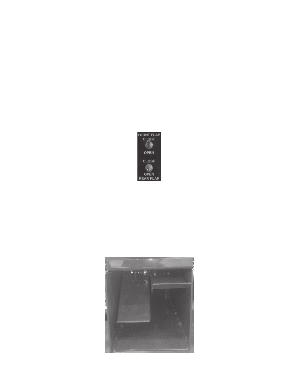
The Brown Ride-on Blower-Vac utilizes two independently controlled airflow
dampers in the air discharge port. This allows the operator to more fully control
the direction of airflow in order to accommodate varying conditions. The damper
control switches are located on the left side of the operator control panel. The
upper switch controls the forward damper and the lower switch controls the
rear damper. The image below illustrates this control interface.
optimal positioning of Brown Ride-On Blower-Vac airflow dampers will
vary based on factors including: terrain; operator preference; nature of
material being moved; engine rpm; forward speed; and distance between
Brown Ride-On Blower-Vac and material being moved. Each operator will
need to experiment with different front and rear damper configurations in
order to achieve the most effective air pattern. The image below illustrates a
configuration that provides downward airflow from the front of the discharge
port and a more level airflow from the rear half of the port. A configuration
such as this may be beneficial for situations such as cleaning curbs, but optimal
positioning will vary per type of operation.
PAGE 12