"pull off"force between silver and ceramic layer, Lead wire, 20n 3.2.b pull force by vertical direction is – BeStar FT-32T-3.1A12 User Manual
Page 4: Fig.1 direction of lead wire (horizontally), Fig.2 direction of lead wire (vertically), Piezo ceramic element
A 09/08/24 汤浩君
A
6
Rev.
Date
B
5
Drawn
Note
FT-32T-3.1A12
DRG NO: BS/TEY01.286A
Piezo Ceramic Element
09/08/24
4
Approved by:
李红元
3
Drawn by:
Checked by:
Date:
汤浩君
赵 峥
2
A
Page:04 of 07
1
B
Notes:
1.Element shall be free from obvious contamination,deep scratches and metal deformation.
2.Tolerance of concentricity between metal disc and ceramic shall be within 0.5mm.
3.All solder points shall be prevented by the isolation glue.
4.Eccentricity of the inner circle and outer circle of metallic plate is 0.3.
5.Eliminate the leaning metallic part,up to ceramics part,to avoid the short circuit with the
metallic ringlet.
6.The number of 200935 at the piezo is the mean that 2009 show the year of manufacture,35
show the period of manufacture in a year.
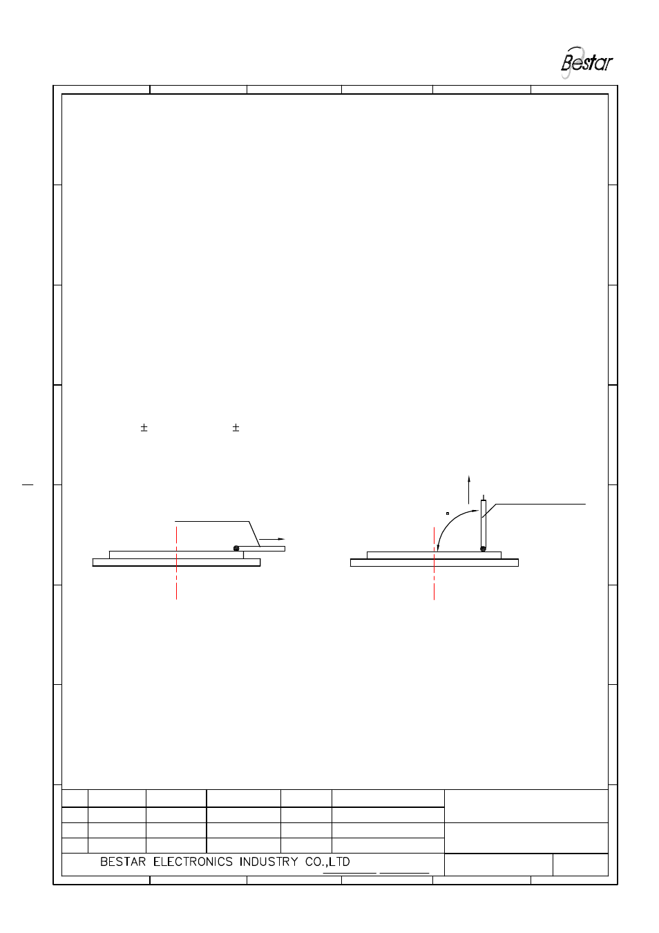
3."Pull off"force between silver and ceramic layer
Note:
3.1 Lead wire (UL 1571 AWG#28)to be soldered on the silver by handsoldering
at 300 10
°C duration 2 0.5 sec
3.2.a Pull force by houizontal direction is
≥
20N
3.2.b Pull force by vertical direction is
≥
2.5N
T
h
is
p
ri
n
t
a
n
d
i
n
fo
rm
a
tio
n
t
he
re
i
n
a
re
p
ro
p
ri
e
ta
ry
t
o
B
e
s
ta
r
E
le
c
tr
o
n
ics
I
ndu
s
tr
y
C
o
.,
L
td.
a
nd
s
h
a
ll
no
t
b
e
u
s
ed
i
n
w
h
o
le
o
r
in
pa
rt
w
ith
ou
t
it
s
w
ri
tt
en
c
on
tent
Lead Wire
FIG.1 Direction of Lead Wire
(horizontally)
C
D
E
F
5
6
FT-32T-3.1A12
G
H
Lead Wire
FIG.2 Direction of Lead Wire
(vertically)
90
C
D
E
F
4
3
2
1
G
H
博 士 達