Baldwin Soho 3_4 Escutcheon Handleset User Manual
Page 2
fold line
fold line
©2010 Baldwin Hardware Corporation, Lake Forest, CA 92610 PK.9010 (2/10)
fold line
fold line
fold line
fold line
fold line
fold line
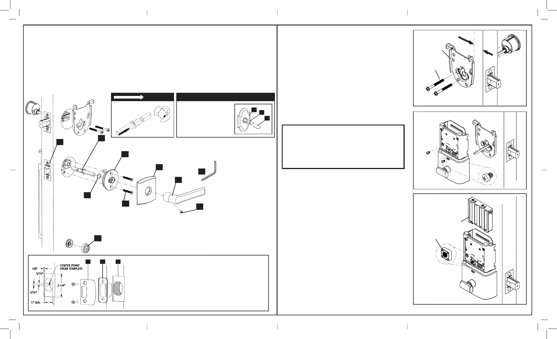
INTERIOR TRIM
DEADBOLT INSTALLATION (requires Keyless Entry Deadbolt)
1. Place spindle (F) into latch (A) with the V-groove pointed to the hinge side of door (see view). Slide spacer (G) over spindle (F).
2. Install adaptor (H) over spindle (F) and secure with adaptor screws (J)
3. Test operation of handleset. If latch does not operate smoothly, loosen screws (E) and (J) and gently lift up the exterior subassembly while
retightening (J) screws. Test operation again.
4. Snap rose (K) onto adaptor. See alternate rose configuration when applicable.
5. Slide lever (L) onto spindle and secure with set screw (M) using supplied allen wrench (Q).
6. Tighten (E) screw and snap screw cover (P) over retainer (D).
See Deadbolt Installation Section
7. Assemble the cylinder, mounting plate and screws as shown.
*Check the vertical alignment for mounting plate (See Figure 1)
8. Using the key, retract and extend the bolt a few times to test for
smooth action.
* If action feels rough:
- Refer to Step 3
- Loosen cylinder screws and re-align the mounting plate
(See Figure 1)
- Test operation of deadbolt and handleset
9. Securely tighten all handleset and deadbolt screws.
10. Install the interior subassembly from the Keyless Entry Deadbolt.
Once flush on door, insert and tighten small screws to secure assembly
onto the mounting plate (See Figure 2)
F
A
G
H
J
K
L
N
P
Q
11. Install batteries into battery pack.
12. Automatic - Bolt Direction Determination Door Handing
(See Figure 3)
a) Press and hold the Program button
b) Insert battery pack
c) The lock buzzer will sound once
d) Release the Program button to enter the Test mode
e) Momentarily press the Program button
The lock will proceed with the Door Handing operation
The Keyless Entry Deadbolt mechanism automatically
determines the “door handing” and sets the proper direction
for the motor to rotate. The system will drive the bolt several
times during this process.
Important before proceeding:
1. Verify that position #2 (Auto-Lock feature) of the “Settings
Switch” is in the OFF position. (Refer to section 10 of Pk.9008)
2. Work with the door open (away from jamb) to avoid accidental
lock out.
3. Make sure the bolt is in the extended (locked) position.
Refer to Keyless Entry Deadbolt product for the Home Connect (HOME
AREA NETWORK (HAN)) instruction sheet for additional programming.
Fig. 1
Fig. 2
Fig. 3
DOOR HINGE
ALTERNATE ROSE CONFIGURATION
1. Place the rose (K) against
the door and thread the re-
tainer (R) onto the adaptor (H).
2. Securely tighten using
supplied spanner wrench (S).
K
R
S
Spindle V-groove
STRIKE INSTALLATION
1. Using the template mark PK.1182 the strike mounting holes and centering points.
2. Overlay strike and trace outline.
3. Mark (2) points, 5/16” above and below center point. Using a 1” spade bit drill 1-1/4”
deep at both points. Chisel out remaining material.
4. Predrill screw holes using 1/8” bit. Chisel outline of strike as shown.
5. Install dustbox (A) and strike (B) with strike screws (C).
C
B
A
Mounting Plate
b) Battery Pack
a) Program Button
Screws
Cylinder