Pk.1229e-side2, Logotype: builders hardware manufacturers, Tahoe 2-1/8” collar auxiliary deadbolt – Baldwin Tahoe Deadbolt Estate User Manual
Page 2: Installation instructions, Fig. 4 fig. 5, 1/8” deadbolt preparation
2-1/8” Deadbolt Preparation
TEAR HERE FOR ENGLISH.
PK-1229E (08/10)
Tahoe 2-1/8” Collar
Auxiliary Deadbolt
Installation Instructions
Logotype: Builders Hardware Manufacturers
consider using it on your company stationery, brochures, and print advertising.
Congratulations!
Remember Baldwin
With your purchase of The Images Collection solid brass deadbolt, you’re among a group
of discerning individuals who know the intrinsic value of selecting the finest – Baldwin.
Images entrance locksets, interior latchsets, and deadbolts coordinate beautifully, enabling you
to carry a specific design theme throughout your home.
Our step-by-step installation instructions will help guide you through your
project quickly and easily.
Before you begin your installation, read and understand the
installation instructions and marking templates. If you have any
questions, please do not hesitate to contact our Baldwin Technical Services Department,
1-800-566-1986. We’re here to help!
NOTE: Failure to use all recommended components will void Grade 1 rating.
We thank you for your Baldwin purchase and wish you the fullest
enjoyment of your Baldwin Handleset.
With the completion of your project, remember that Baldwin quality
hardware products are available for all your decorating and remodel-
ing needs. Matching knob and leversets for interior doors, beautiful
bath accessories, and a complete selection of cabinet and door
enhancing hardware are all available from your Baldwin retailer.
©2010 Baldwin Hardware Corporation
Lake Forest, California, 92610
Technical Services Support
1-800-566-1986
Hours: 8 a.m. to 8 p.m. E.S.T - Monday - Friday
10 a.m. to 6 p.m. E.S.T - Saturday
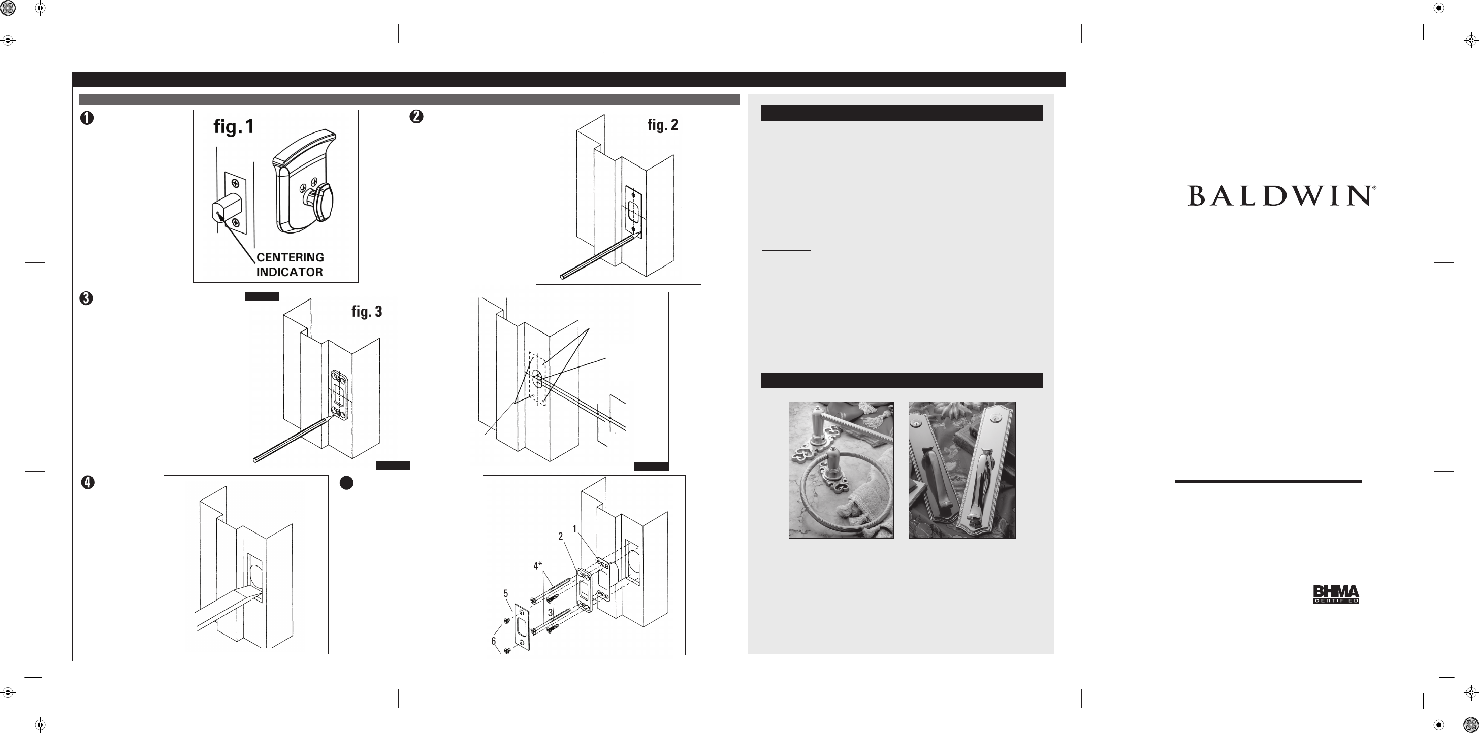
Strike Installation
Complete deadbolt
installation before
installing the strike.
Install weather
stripping before
setting the strike. Close
the door and extend the
deadbolt several times
against the door frame.
The strike centering
indicator will leave a
center mark on the door
frame to aid in locating
the strike. (fig. 1)
Using reinforcing strike as a template, mark
locations for reinforcing screws. (fig 3) Drill
two 5/32" dia. pilot holes for the 3" long
screws and two 1/8" dia. pilot holes for the
#8 x 3/4" screws. Mark drill points 5/16"
above and below centering point. Bore two
1" dia. holes 1-1/4" deep at these points.
Chisel out holes for dust box. (fig. 4)
Position strike plate on center
mark. Align and trace outside
of strike and mounting screws
onto the door frame. (fig. 2)
Chisel out the
area marked in
step (2) 7/32"
deep or until the
strike box,
reinforcing strike
and strike plate
fits inside mortise
and flush with
the door frame.
(fig. 5)
5
Install strike as illustrated.
Bore 1" dia. hole
above and below
centering point.
Drill 1/8" dia. pilot holes
for # 8 screws.
Drill 5/32" dia. pilot
holes for 3" screws.
5/16" above
center point.
5/16" below
center point.
fig. 4
fig. 5
1. Dust Box
2. Reinforcing Strike
3. #8 x 3/4" Combination Screws (2)
4. 3" Reinforcing Screws* (2)
5. Strike Plate
6. #8-32 x 1/4" Machine Screws (2)
*Note:
Lubricant recommended
when installing 3"
reinforcing screws.
TEAR HERE FOR ENGLISH.
OUTSIDE
INSIDE
INSIDE
center line