Standard furnace installation general installation, Furnace / vent - cutouts, Ducting – atwood 8000-II Series Furnace User Manual
Page 2
2
Spacing of 1/4˝ to ducting within 3 feet of furnace must be provided
unless UL listed wire bound vinyl ducts are used. All ducting material
should be rated for continuous use of 200˚F.
NOTE
: If zero clearance is maintained from furnace to cabinet structure, a
4˝ x 4˝ air intake cutout must be provided to blower wheel side of furnace
at air intake opening.
NOTE
: Clearances are specifically for plywood or similar building
materials surrounding the furnace (i.e. furnace should
NOT
be located
under furniture or in a closet space where clothing or other material
could be located.)
NOTE
: Furnace efficiency rating is a thermal rating determined under
continuous operating conditions, independent of any installation. Eff.
rate is given at 77% minimum, actual efficiency rating may be higher.
*When furnaces are installed to minimum clearances, an additional 16 in
2
of return air must be provided to blower side of furnace, or a 2˝ clearance
the full length and height on blower side must be maintained.
ƽ
WARNING
CARBON MONOXIDE POISONING
•
Furnace must be installed and vented to these instructions.
•
Improper installation, adjustment, alteration, service or maintenance
can cause injury or property damage.
•
Improper installation location may cause furnace to produce negative
pressure, affecting combustion air or venting of other appliances.
ƽ
CRITICAL INSTALLATION WARNINGS
•
DO NOT
install furnace on material that restricts return air, like carpet
or any soft material such as vinyl.
•
DO NOT
install where clearance to combustibles cannot be maintained.
•
DO NOT
modify furnace in any way.
•
DO NOT
alter furnace for a positive grounding system.
•
DO NOT
HI-POT furnace unless electronic ignition system (circuit
board) has been disconnected.
•
DO NOT
use battery charger to supply power to DC model furnace
even when testing.
•
DO NOT
use 120 volt AC current with DC models.
•
DO NOT
use furnace cabinet area as a storage compartment.
•
DO NOT
vent furnace with venting system serving another appliance.
•
DO NOT
vent furnace to an outside enclosed porch area.
•
DO NOT
use for temporary heating of buildings or structures under construction.
•
Protect building materials from degrading from flue gas exhaust.
•
Protect furnace electrical components from water.
USA AND CANADA
-
FOLLOW ALL APPLICABLE STATE AND LOCAL CODES
-
IN THE ABSENCE OF LOCAL CODES OR REGULATIONS
,
REFER TO CURRENT STANDARDS OF
:
•
Recreation Vehicles ANSI 1192/NFPA 1192.
•
National Fuel Gas Code ANSI Z223.1 /CAN/CGA B149 Installation Codes
•
Federal Mobile Home Construction & Safety Standard, Title 24 CFR, part
3280, or when this Standard is not applicable, the Standard for Manufactured
Home Installations (Manufactured Home Sites, Communities and Set-Ups),
ANSI A255.1 and/or CAN/CSA-Z240 MH Series, Mobile Homes.
•
Ground - National Electrical Code ANSI/NFPA No. 70 and/or CSA C22.1
•
Park Trailers ANSI 119.5
NOTE
: The direct high voltage spark ignition generates a radio frequency
that could cause interference with other microprocessor based equipment.
Locate equipment at least five feet from furnace location. If this distance can-
not be maintained, purchase KIT MPD 37773 (a shielded high voltage lead).
ƽ
WARNING
CARBON MONOXIDE POISONING
•
Properly seal vent cap to side wall to prevent carbon monoxide from
entering coach.
•
DO NOT
draw
combustion air from living area.
DO NOT
vent exhaust air
into the living area or an enclosed porch.
Return air is supplied through openings in furnace grille. The return air passage
must be kept clear for furnace to function properly. Refer to
MINIMUM CLEARANCE
TO FLOORBOARDS
,
WALLS
& SIMILAR COMBUSTIBLE BUILDING MATERIAL
.
STANDARD FURNACE INSTALLATION
General Installation -
LOCATION
•
Install extension box and vent cap through an exterior wall.
•
DO NOT
install furnace near tilt-out rooms, slide-outs, doors or other
projections that could obstruct furnace exhaust.
•
Locate furnace near midpoint of coach for single furnace applications.
•
DO NOT
install vent in areas where projections or door openings come
within 6˝ of vent tube opening.
•
DO NOT
install furnace in an area where wires, pipes, or other objects
will interfere with installation or operation of furnace.
•
It is not recommended to install furnace on material that restricts
return air, such as directly on carpet, or soft material (like vinyl).
•
If you must install furnace on carpet or soft material, install furnace on
cleats, or on a wood or metal panel extending the full width and depth
of furnace plus minimum clearances to combustibles.
Installation Procedure
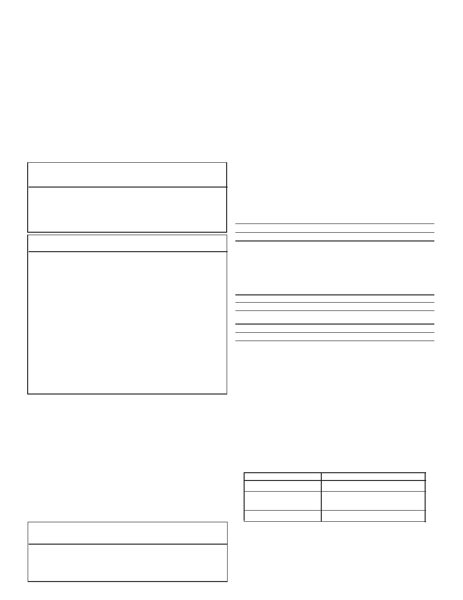
ZERO CLEARANCE - AIR INTAKE CUTOUT
(
FIG
1
)
AIR INTAKE OPENING SIDE OF THE BLOWER WHEEL
CUT OUT DIMENSION
A
B
C
D
CABINET WALL
2-3/4˝
3-5/8˝
4˝
4˝
A 4˝ x 4˝ cabinet cut out must be provided when there is zero clearance
between furnace and cabinet structure.
1. Set aside combustion air box and exhaust tube extensions for instal-
lation from outside coach.
FURNACE / VENT - CUTOUTS
(
FIG
.
2
)
CUT OUT DIMENSION
A
B
INTERIOR CABINET WALL
8-3/8˝
11-1/4˝
DO NOT OVERSIZE HOLE
-
OVERSIZING CAN RESULT IN WATER LEAKAGE
CUT OUT DIMENSION
C
D
E
COACH EXTERIOR WALL FOR VENT
4-7/8˝
2-1/2˝
1-3/4˝
DUCTING
(
FIG
.
3
)
Proper duct installation is critical to operation of furnace. When
installing ducts, use materials rated for continuous use at 200˚F. Front
discharge temperature should not exceed 250˚F.
Flexible Ducting System
When designing Flexible Duct Systems:
•
avoid sharp bends or crushed ducts
•
stretch all ducts and run them directly to outlets, keeping quantity
and angles of bends to a minimum
2. A variety of vent kits are available to provide the correct venting from fur-
nace to outside of vehicle. To determine
VENT LENGTH
(V
DIM
), measure the
distance from the back of furnace casing to outside vehicle side wall. For
proper vent kit check your V
DIM
on
VENTING CHART
.
3. Ducting available:
TYPE OF DISCHARGE
REMOVE
SIDE ONLY
duct covers from both sides
COMBINATION
front discharge cover plate
FRONT
& SIDE
and side duct cover plate
FRONT ONLY
front discharge cover plate
See
DUCTING CONFIGURATIONS
for covers and their locations.
4. Install the furnace through cutout in cabinet area. Secure furnace
with two screws
FIG
5-A.
OPTIONAL - Installation: The 79-II furnace may be installed in a
cabinet behind a return air grille
FIG
4-I. Door MUST be on furnace.
Return air grille must supply a minimum of 35 in
2
of open area and