Associated Equipment 6001A User Manual
Page 3
20.
GROUNDING AND AC POWER CORD CONNECTION INSTRUCTIONS
The charger should be grounded to reduce the risk of electric shock. This charger is equipped with an electric cord having an equipment
grounding conductor and a grounding plug. The plug must be plugged into an outlet that is properly installed and grounded in accordance with
all local codes and ordinances.
DANGER.
Never alter the AC cord or plug provided - if it will
not fit the outlet, have a proper outlet installed by a qualified
electrician. Improper connection can result in a risk of an
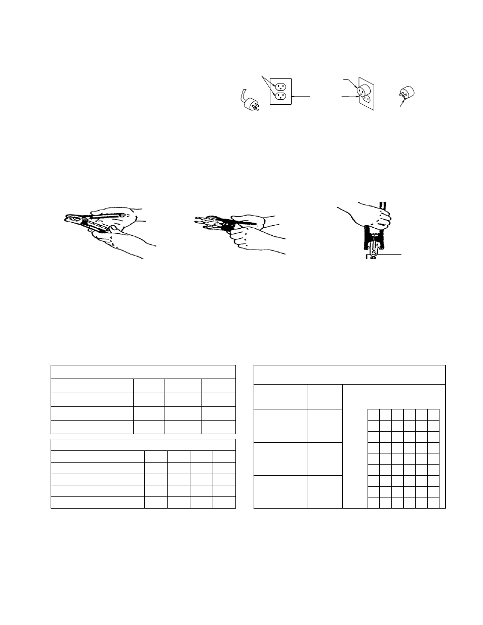
electric shock. This battery charger is for use on a nominal
120-volt circuit, and has a grounding plug that looks like the
plug illustrated in FIGURE (A). A temporary adapter, which
looks like the adapter illustrated in FIGURE (C), may be used
to connect this plug to a two-pole receptacle, as shown in FIGURE (B), until a properly grounded outlet can be installed by a qualified
GROUNDED
OUTLET
GROUNDING METHODS
GROUNDING
MEANS
ADAPTER
COVER OF GROUNDED
OUTLET BOX
(A)
(B)
(C
ADAPTER
)
electrician.
DANGER.
Before using an adapter as illustrated, be certain that the center screw of the outlet plate is grounded. The green-colored rigid
ear or lug extending from the adapter must be connected to a properly grounded outlet - make certain it is grounded. If necessary, re
original outlet cover plate screw with a longer screw that will secure the adapter ear or lug to the outlet cover plate and make groun
connection to grounded outlet. NOTE:
USE OF AN ADAPTER IS NOT ALLOWED IN CANADA. IF A GROUNDING TYPE
RECEPTACLE IS
place the
d
NOT AVAILABLE, DO NOT USE THIS APPLIANCE UNTIL THE PROPER OUTLET IS INSTALLED BY A QUALIFIED
21.
For instructions for NEGATIVE clamp attachment
refer to section 18f or 18g.
22.
e of battery and state of charge per charts
d.
uld be
approximately 125
°F. Do not overcharge batteries. Overcharging results in excessive water loss and eventual damage to the battery.
ELECTRICIAN.
NOTE: SIDE TERMINAL TO BE USED IN POSITIVE CLAMP ONLY!
Storage position
Will not get lost. Always ready to use.
ed,
holds adapter firm. Will not slip back.
spring
nsion holds adapter firm.
battery is determined to be defective.
Extended position
Note: Pressure, when handle is squeez
Thrust on terminal
Note: Clamp is released and
te
LENGTH OF CHARGE
a.
Test the battery for state of charge. Do not charge if it is over 75% charged or the
b.
Set beginning amps charge rate for siz
c.
Charge for length of time per charge,
Discontinue charge when the specific gravity of electrolyte reaches 1.260 or above. A temperature compensating hydrometer sho
used for this reading. Discontinue charge if the battery begins to gas excessively or if the temperature of the electrolyte reaches
23.6
11.8
5.9
1.110
23.8
11.9
5.95
1.140
24.2
12.1
6.05
1.185
24.8
12.4
6.2
1.225
25%
50%
75%
DEAD
Open Circuit Voltage-24 V.
Open Circuit Voltage-12 V.
Open Circuit Voltage-6 V.
Specific Gravity
STATE OF CHARGE
STATE OF CHARGE TABLE
Cold Cranking Amps
Reserve Capacity
Ampere Hours
BATTERY SIZE
60
90
350
80+
100+
400+
40
60
275
BATTERY SIZE TABLE
LARGE
MEDIUM
SMALL
BATTERY SIZE %CHARGE
0-25
30
30
30
45
45
50
20
20
20
30
35
40
5
5
20
25
15
25
20
35
55
15
25
45
10
20
30
20
40
55
15
30
50
10
20
30
30
60
90
25
45
70
15
30
45
15
15 15 15
10
10
10 10 10
15 30 45 60 75 90
A
M
P
E
R
E
S
SMALL
MEDIUM
LARGE
CHARGE RATE Vs. MINUTES CHARGE
25-50
50-75
50-75
25-50
0-25
50-75
25-50
0-25
MINUTES
3