Wiring diagram, Modèle ess6008 – Associated Equipment ESS6008 Manual User Manual
Page 4
4
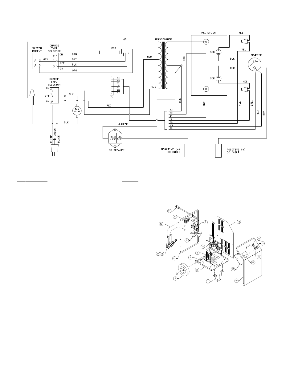
WIRING DIAGRAM
MODEL ESS6008 REPAIR PARTS
Item Description
Part No.
1
Front Leg.......................................................... 605671
2 Axle
w/nuts....................................................... 610052
3 Wheel
w/nuts (2) .............................................. 611157
4 Rectifier
w/wiring harness ................................ 611217
5 Transformer ..................................................... 611218
6 Fan
Blade......................................................... 610189
7 Fan
Motor w/blade ........................................... 610190
8 DC
Circuit Breaker ........................................... 610536
9 Switch............................................................... 610291
10
Switch
ON-OFF-ON ......................................... 611167
11
AC
Cord ........................................................... 611185
12
DC
Cable Set ................................................... 611219
13
Clamps
(1
pair w/jaws) ......................................... 6199
14
Jaw Kit (repairs 1 clamp).................................. 610970
15
PCB.................................................................. 611155
16
Ammeter .......................................................... 605204
17
Back
Panel ....................................................... 610977
18
Right
Side Panel .............................................. 611032
19
Front
Panel....................................................... 611220
20
Base
Panel....................................................... 610054
21
Switch
Momentary............................................ 610263
Parts Not Shown
Left Side Panel................................................. 611031
Top Panel......................................................... 611011
Handle.............................................................. 610753
Clamp Bar........................................................ 610517
MAINTENANCE INSTRUCTIONS
Worn clamps should be replaced. Worn parts can lead to poor connections and present a safety hazard. See parts list for part number of D.C. Cord kit.
Any Maintenance or repair of this unit that involves disassembly of the cabinet should be done only by a qualified serviceman. Incorrect reassembly may
result in a risk of electric shock when the unit is subsequently used.
MODÈLE ESS6008