Wiring diagram, Odel 6007a repair parts m, Maintenance instructions – Associated Equipment 6007A User Manual
Page 4
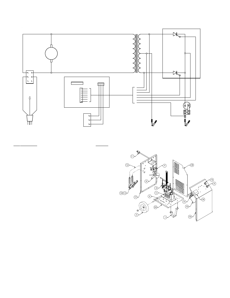
WIRING DIAGRAM
4
ODEL 6007A REPAIR PARTS
M
Item Description
Part No.
1
Front Leg.......................................................... 605671
2 Axle
w/nuts....................................................... 610052
3 Wheel
w/nuts (2) .............................................. 611157
4 Rectifier
w/wiring harness ................................ 610985
5 Transformer ..................................................... 611168
6 Fan
Blade......................................................... 610189
7 Fan
Motor w/blade ........................................... 610190
8
DC Circuit Breaker (2) ...................................... 610987
9 Switch............................................................... 610291
10
Switch
ON-OFF-ON ......................................... 611167
11
AC
Cord ........................................................... 610696
12
DC
Cable Set ................................................... 610820
13
Clamps (1 pair w/jaws) ........................................ 6199
14
Jaw Kit (repairs 1 clamp).................................. 610970
15
PCB.................................................................. 611155
16
Ammeter .......................................................... 610346
17
Back
Panel ....................................................... 610977
18
Right
Side Panel .............................................. 611032
19
Front
Panel....................................................... 611166
20
Base
Panel....................................................... 610054
Clamp Bar ........................................................ 610517
e cabinet should be done only by a qualified serviceman. Incorrect reassembly may
result in a risk of electric shock when the unit is subsequently used.
Parts Not Shown
Left Side Panel................................................. 611031
Top Panel......................................................... 611011
Handle.............................................................. 610753
BL
AC
K
FAN MOTOR
POSITIVE (+)
DC CABLE
NEGATIVE (-)
DC CABLE
RED
AMMETER
LT
BLU
E
JUM
P
E
R
RECTIFIER
YELLOW
SCR1
GR
AY
PCB
WHITE
J1
1[ON]
POWER
GRE
E
N
W
H
ITE
BL
AC
K
0[OFF]
1
BLACK
BL
AC
K
OR
A
N
GE
SCR2
TRANSFORMER
BR
O
W
N
DC CIRCUIT
BREAKERS
BLK
ORG
GRY
LBU
YEL
BWN
RED
BLAC
K
CHARGE
TYPE
SELECTOR
ON
OFF
ON
BWN
GRY
BLK
3
1
2
3
1
2
6
4
5
MAINTENANCE INSTRUCTIONS
Worn clamps should be replaced. Worn parts can lead to poor connections and present a safety hazard. See parts list for part number of D.C. Cord kit.
Any Maintenance or repair of this unit that involves disassembly of th