Wiring diagram, Model 9425 repair parts – Associated Equipment 9425 User Manual
Page 4
4
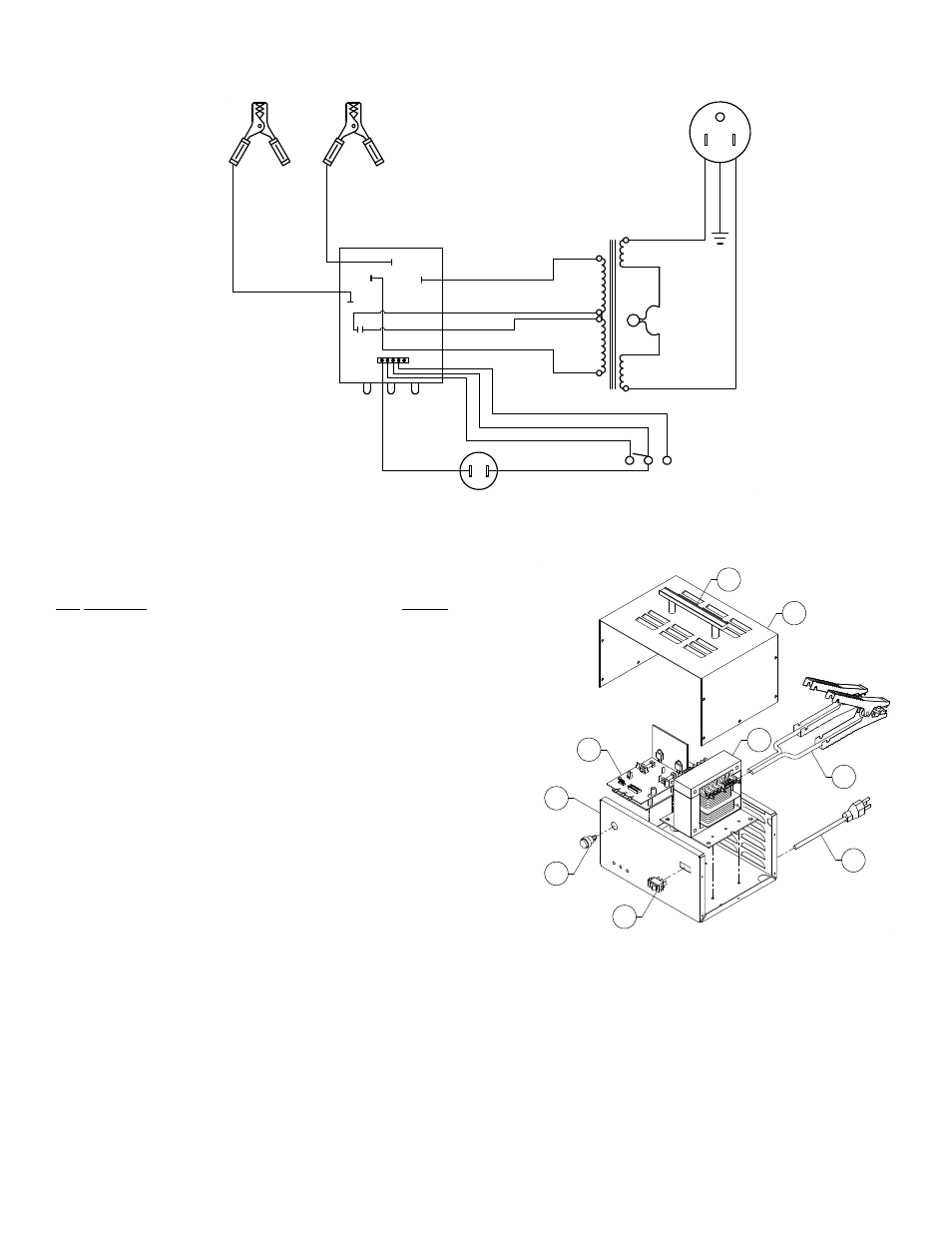
WIRING DIAGRAM
J8
J7
AC1
AC2
B+
B-
9
1
GR
OUN
D
14.2V SEALED
19
20
21
22
WHITE
RED
RED
WHITE
RED
BLACK
CIRCUIT BOARD
13.7V ESS/FLASH
DC LEADS
AC CORD
FLOODED
TRANSFORMER
GREY
BLACK
BROWN
GR
E
E
N
BL
A
C
K
WH
IT
E
CHARGE SWITCH
GREY
MOMENT. SWITCH
ORG
J4
1
MODEL 9425 REPAIR PARTS
Item Description Part
No.
1
Handle......................................................................... 610619
2 Cabinet
top.................................................................. 610755
3 Transformer................................................................. 611169
4 Circuit
board................................................................ 610926
5
Battery type switch ...................................................... 611000
6 Cabinet
base ............................................................... 611315
7 AC
Cord ...................................................................... 610928
8 DC
Cables................................................................... 610886
9 Momentary
Switch....................................................... 611316
MAINTENANCE INSTRUCTIONS
Worn parts can lead to poor connections and present a safety hazard. See parts list
for part number of DC Cable kit.
Any Maintenance or repair of this unit that involves disassembly of the cabinet should
be done only by a qualified serviceman. Incorrect reassembly may result in a risk of
electric shock when the unit is subsequently used.
7
8
4
3
2
1
6
5
9