Minimum and maximum airflow settings, Altitude correction factors – Anemostat EZT User Manual
Page 11
1220 Watson Center Road • Carson, CA 90745
Tel: (310) 835-7500 • Fax: (310) 835-0448
www.anemostat.com • [email protected]
11
Minimum and Maximum Airflow Settings
REFER TO THE CONTROLS MANUAL CM-1 FOR THE PROPER FIELD ADJUSTMENT
OF THE MINIMUM AND MAXIMUM AIRFLOW SETTINGS ON TERMINALS PROVIDED
WITH PRESSURE INDEPENDENT CONTROLS.
Some adjusting tips:
1. Allow sufficient time for the controller to respond to adjustments.
2. Cycling of the thermostat to check maximum and minimum airflow settings is often
required.
3. On units with pneumatic controls, do not turn the adjustment knobs excessively.
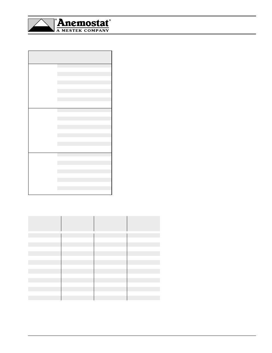
Altitude Correction Factors
Barometric
Pressure
Altitude
Density
Correction
(in h.g.)
(feet)
lb/ft3
Factor
29.92
0
.075
1.03
20.28
500
.074
1.01
28.85
1000
.072
0.99
28.33
1500
.071
0.98
27.82
2000
.070
0.96
27.32
2500
.068
0.95
26.81
3000
.067
0.93
26.33
3500
.066
0.91
25.84
4000
.065
0.89
25.37
4500
.064
0.88
24.89
5000
.062
0.86
24.44
5500
.061
0.85
23.98
6000
.060
0.83
23.54
6500
.059
0.82
23.09
7000
.058
0.80
Example: Determine the airflow sensor signal of a 6” unit at 500 CFM located
at an elevation of 5000 ft., for a 3000 series pneumatic controller.
To use the correction factor:
Correction factor X CFM at unit location = .86 x 500 = 430 CFM
Referencing the 6” flow curve, shown on page 10, find 430 CFM @ .80” w.c.
sensor signal pressure. The velocity controller set at .80” signal pressure will
result in 500 CFM at 5000 ft. elevation.
Notes:
1. Minimum and maximum airflow with pressure independent controls based on the
following
flow sensor signals:
Model 51 Controller - 1 VDC – 10 VDC
Model 31 Controller - 0.03” w.g. – 1.0” w.g.
Models 23, 24 Controllers - 0.04” w.g. – 1.0” w.g.
2. Settings below the minimum are not recommended for accurate control when using
pressure independent controls. Minimum airflow for pressure dependent applications is
0 cfm.
3. Pressure independent controls may be set for 0 CFM, at or above the minimum airflow
shown in table 4, but not between.
4. Model 23 controller available as direct acting for normally open or model 24 controller
available as reverse acting for normally closed damper positions. Factory set non-field
adjustable start point and reset span.
5. Model 31 controller can be used either as direct or reverse acting for normally open or
normally closed damper positions. Field adjustable start point and reset span.
6. Models 23, 24, 31 controllers equipped with separate adjustable knobs for maximum
and minimum airflow settings.
7. Model 51 electronic analog controller maximum and minimum airflow settings field
adjustable at the thermostat.
Control
Inlet
Min Airflow
Max Airflow
1
Type
Size
(CFM)
(CFM)
Model 51
5
22
305
Electronic
6
45
470
Analog
7
70
635
Controller
8
90
835
9
115
1100
10
145
1355
12
155
1740
14
250
2300
16
447
3390
24x16
650
6480
Model 31
5
50
287
Pneumatic
6
81
469
Controller
7
106
612
8
150
867
9
190
1098
10
234
1353
12
312
1802
14
428
2469
16
583
3366
24x16
1101
6358
Models 23, 24
5
57
287
Pneumatic
6
94
469
Controllers
7
122
612
8
173
867
9
220
1098
10
271
1353
12
360
1802
14
494
2469
16
673
3366
24x16
1272
6358
1
Airflow rates above maximum shown are available. Contact your Anemostat representative for application assistance.