ABUS TVIP31550 User Manual
Page 85
85
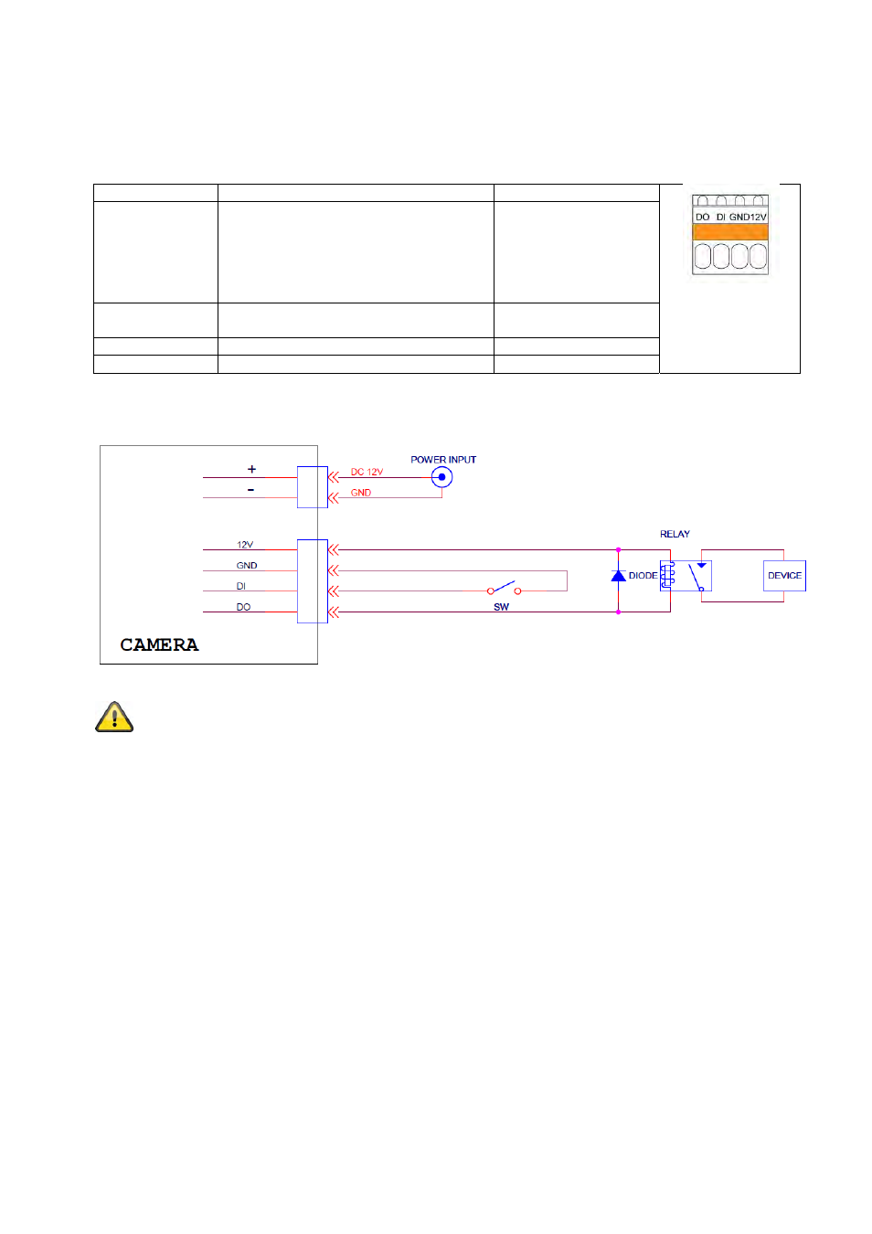
4.4 Alarm input and output
Adhere to the following connections and maximum loads for the digital
alarm input and output.
Connection Description
Max. load (V/A)
DO – Alarm
output
Connection of a transistor or relay:
Transistor: NPN with emitter against
ground (GND)
Relay:
12 VDC “and” connection,
plus DO with diode
(see example below)
24 VDC, 100 mA
DI – Alarm input
Activation of the digital input by con-
necting the DI and GND connections
-
GND Ground
connection
-
12 VDC
Voltage output
12 VDC, max. 100 mA
Connection example:
Please carefully observe the connection instructions and power specifications!
4.5 Setting the focus
TVIP31000, TVIP31050, TVIP31500 and TVIP31550 cameras are equipped with a fixed lens. The zoom is
fixed on these cameras. However, the focus can be adjusted here by turning the lens by hand when required.