ABUS TVCC20000-TVCC20541 User Manual
Page 21
21
6.4 Mounting of the camera
For the mounting of the camera, mount the provided socket at the upper or underside of the
camera. For this the plate is aligned with the already predefined screw openings and fastened with
the enclosed screws.
In case of installation inside an outdoor housing, the provided spacer will be installed between
camera and socket.
ATTENTION!
During the assembly the camera must be separated from the mains voltage.
CAUTION!
The camera should not be positioned with opened iris towards the sun. This can lead
to the destruction of the sensor.
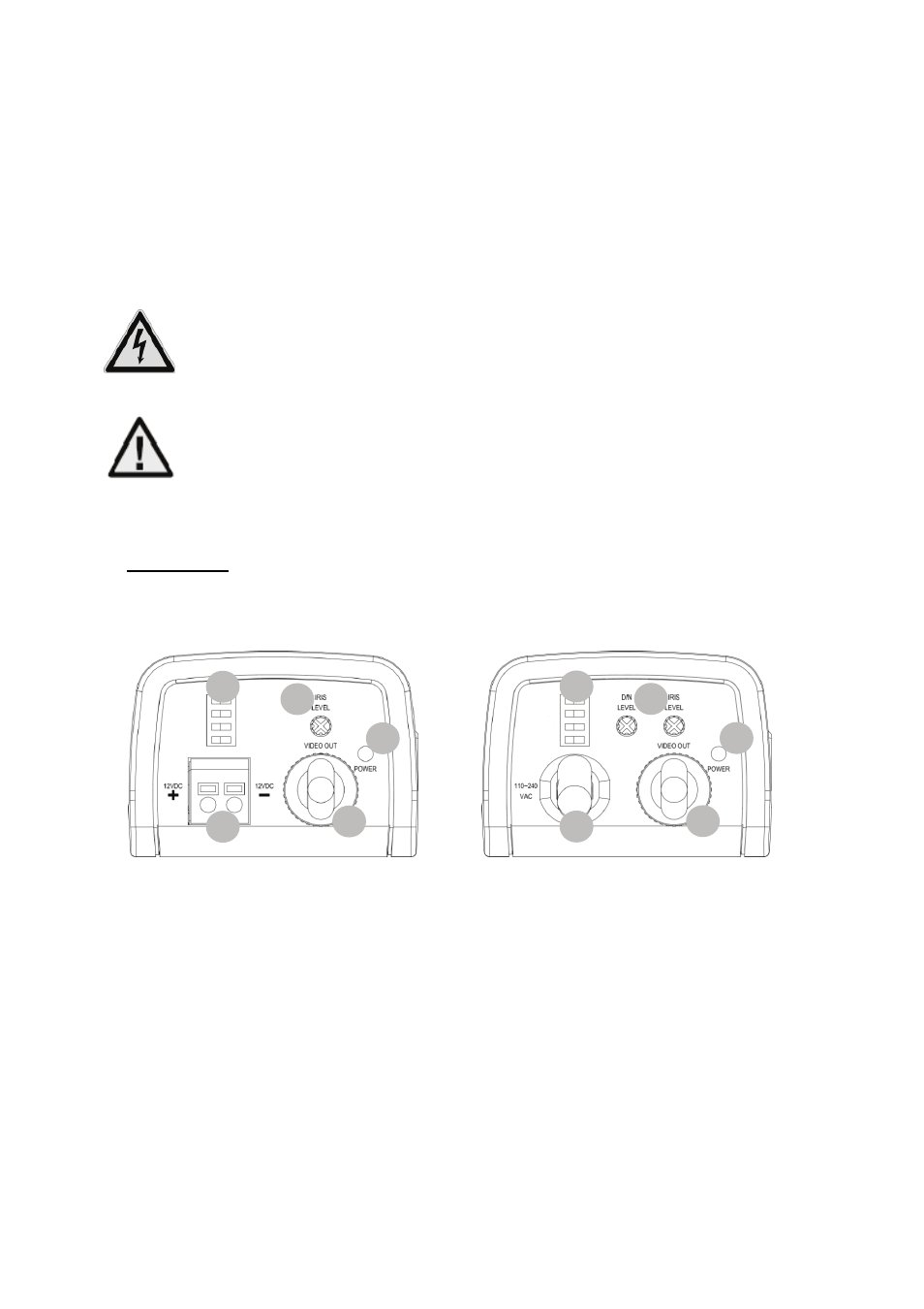
7. Rear view
7.1 Adjustment of the DIP-switches
12VDC Version
110~240VAC Version
(1) DIP-Switches
(2) Potentiometer
(3) Power Supply (12VDC or 110~240VAC)
(4) BNC-Video Output (VIDEO OUT)
(5) Status LED (active if power connected)
2
1
5
3
4
2
1
5
3
4
- CASA30400 (46 pages)
- CASA30500 Quick installation instructions (44 pages)
- TVIP10005B (125 pages)
- TV7181 (44 pages)
- TVCC40531 (75 pages)
- TV7511 (54 pages)
- TV7018 (56 pages)
- TVCC12020 (28 pages)
- TVCC12010 (48 pages)
- TVCC40010 (104 pages)
- TVCC34010 (104 pages)
- TVIP61500 Operating instructions (487 pages)
- TVIP61500 Quick operating instructions (124 pages)
- TVCC40000–TVCC40030 (62 pages)
- TVIP41500 Operating instructions (498 pages)
- TVCC35500 (63 pages)
- TVCC70000 (83 pages)
- TVCC75100 (248 pages)
- TVCC60000-TVCC60030 (84 pages)
- TV3210 (171 pages)
- TVVR30004 Operating instructions (569 pages)
- TVVR30004 Quick operating instructions (162 pages)
- TVAC15000B (87 pages)
- TVAC16000B (139 pages)
- TVAC15010B (44 pages)
- TVAC16010B (43 pages)
- TVAC80010B (68 pages)
- TVVR11002 (134 pages)
- TVAC710x0 (90 pages)
- TV6700 (60 pages)
- TVAC35500–TVAC35520 (52 pages)
- TVAC35600 (48 pages)
- TVAC21000 (98 pages)
- TVAC10000 (92 pages)
- TVAC10100 (76 pages)
- TVAC10041 Operating instructions (99 pages)
- TVAC10041 Quick operating instructions (50 pages)
- TVAC10050 Operating instructions (117 pages)
- TVAC10050 Quick operating instructions (50 pages)
- TVAC10021 Operating instructions (105 pages)
- TVAC10021 Quick operating instructions (50 pages)
- TV8740 (24 pages)
- TVVR41220 Quick operating instructions (87 pages)
- TVVR41220 Operating instructions (409 pages)
- TVAC312x0 Quick operating instructions (146 pages)