ABUS TVAC35500–TVAC35520 User Manual
Page 20
20
English
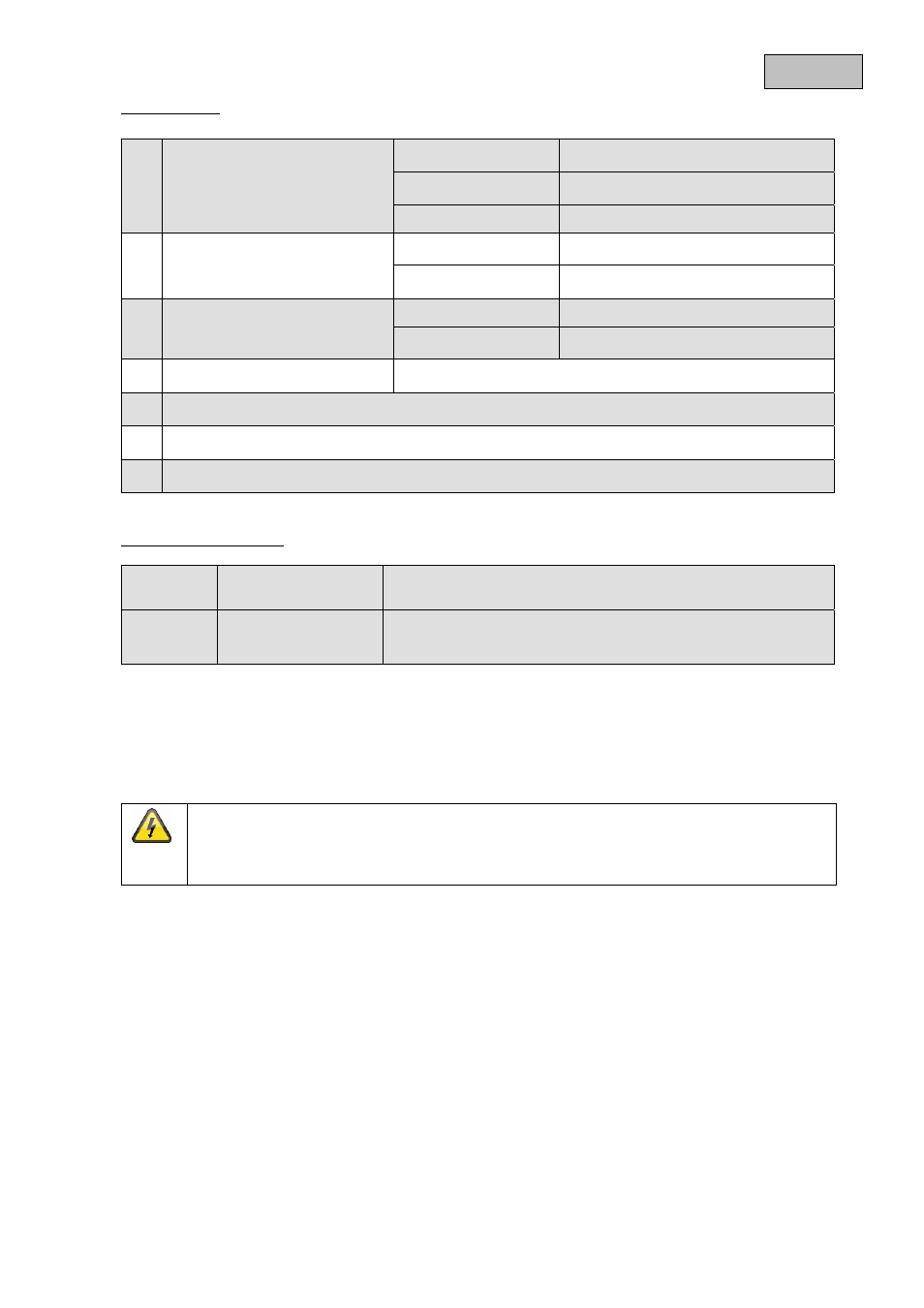
Connections:
LED control indicator:
6. Installation
6.1 Mounting
This device is designed for a fixed indoor installation. Fasten the device securely and with the correct
alignment so that a minimal clearance is achieved. Allow at least 100 mm between this device and other
equipment.
Use the holes in the base for feeding the cable into the housing.
Route input and output cables via different knockouts or cable entry holes.
6.2 Connecting to the mains power supply
Connect to an external mains isolation device rated at 3A minimum, for example a fused spur, using a
cable suitable for connecting to the mains power supply (Ø 0.5 mm², 300/500 V ac).
Use suitable cable connections during the installation. Ensure that cable ties are used for all cables.
c
Mains connection block
Brown cable
Live
Green/yellow cable
Ground
Blue cable
Neutral
d
Battery connection
Red cable
Positive
Black cable
Negative
e
Power connections 1 – 8
Connection “+”
Positive
Connection “-”
Negative
f
Tamper contact
Contact closed when cover closed (NC = normally closed)
g
Battery fuse
h
Power unit fuse
i
Mains fuse
GREEN
Mains LED
The power supply is working correctly
RED
Fault LED
Fault present:
Output fuse or battery fuse is defective
(TVAC35500 and TVAC35510 only)
IMPORTANT:
Only connect the device to the mains power supply after it has been installed.
The device must be earthed at the start of installation.