AAEON ACP-5185 User Manual
Page 84
M u l t i - T o u c h P a n e l P C
A C P - 5 1 8 5
Appendix A Programming the Watchdog Timer A-2
A.1 Programming
ACP-5185 utilizes ITE 8781 chipset as its watchdog
timer controller. Below are the procedures to complete its
configuration and the AAEON initial watchdog timer
program is also attached based on which you can
develop customized programs to fit your application.
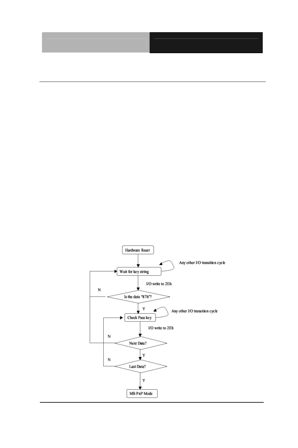
Configuring Sequence Description
After the hardware reset or power-on reset, the ITE 8781 enters the
normal mode with all logical devices disabled except
KBC. The initial state (enable bit ) of this logical device (KBC) is
determined by the state of pin 121 (DTR1#) at the falling edge of
the system reset during power-on reset.