AAEON ACP-5187 User Manual
Page 26
M u l t i - T o u c h P a n e l P C
A C P - 5 1 8 7
Chapter 2 Hardware Installation
2-5
6 NC
7 NC
8 NC/+5V/+12V PWR +5V/+12V
9 GND GND
Note: COM2 RS-232/422/485 can be set by BIOS setting. Default is
RS-232. Pin 8 function can be set by JP8.
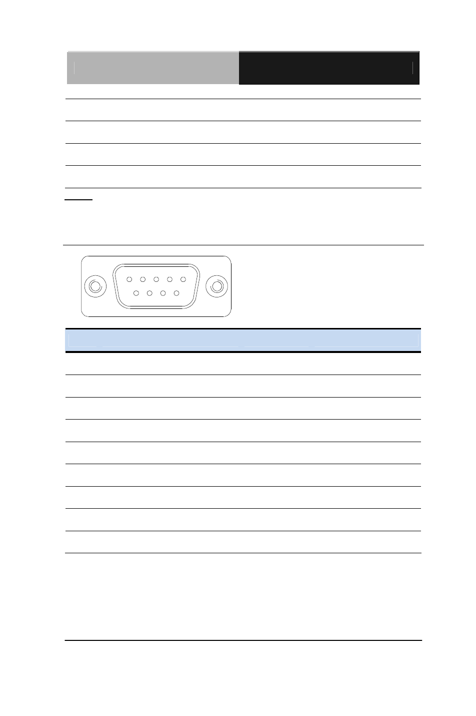
2.5 COM Port 1 (D-SUB 9) (CN27)
1
5
6
9
Pin
Pin Name
Signal Type
Signal Level
1 DCD
IN
2 RX
IN
3 TX OUT
±9V
4 DTR OUT ±9V
5 GND GND
6 DSR
IN
7 RTS OUT
±9V
8 CTS
IN
9 RI
IN