Elmo Rietschle V-DTR 100/140 User Manual
Page 13
13
www.gd-elmorietschle.com © Gardner Denver Schopfheim GmbH, Gardner Denver Deutschland GmbH
|
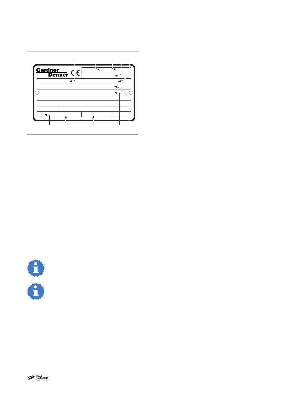
Bauj./Nr. 09
S1 5,50 / 6,50
kW
Typ DTR 100 (01)
+ 0,5 bar
2843973
100 / 120 m³/h
EN 60034
1460 / 1745 min
-1
1027620113
3~
Mot.
Set up and operation
6
1
7
8
9
10
3
4
5
2
4.2 Description
The V-DTR range has a connecting thread on the pressure side and a protective cap on the suction side.
The aspirated air is cleaned by an inbuilt fi ne micro fi lter. The carbon dust caused by the scoring of the
blades can also be separated by an integral fi lter if necessary. A fan between the compressor housing and
the motor provides intensive air cooling. The compressor housing is located in a sound cover. The com-
pressed air is cooled by a cooling segment.
The compressor is driven by standard fl anged three-phase motors using a coupling.
The pressure regulating valve (Fig. 2/D) is used to set the pressure to the required values with an upper limit.
4.3
Areas of application
These dry running rotary vane compressors, V-DTR 100 and V-DTR 140,are suitable for creating excess
pressure between 0 and the maximum limit (in bars) given on the data plate Fig. 2/N). Constant operation is
permissible.
The compressors have a nominal fl ow rate of 100 and 140 m
3
/h at 50 Hz. The load limits (bars) on the pres-
sure side are given on the data plate (N). Data sheet D 361 shows the dependency of the fl ow rate on the
excess pressures.
These dry running machines are suitable for conveying air with a relative humidity of 30 - 90%.
If the unit is switched on more frequently (at regular intervals of about 10 times an hour) or at
higher ambient temperatures and intake temperatures, the excess temperature limit of the motor
winding and the bearings may be exceeded.
Please contact the manufacturer should the unit be used under such conditions
If it is installed in the open air the unit must be protected from environmental infl uences, (e.g. by a
protective roof).
1
Type/ Size (mechanical version)
2
Year of construction
3 Motor
design
4 Serial
number
5 Item
no
6
Final pressure (abs.)
7 Capacity
50
Hz / 60
Hz
8 Speed
50
Hz / 60
Hz
9
Motor output 50 Hz / 60 Hz
10 Operating
mode
4.1.1 Data plate
Fig. 3 Data plate