Figure d, Figure c, Figure a – Liberty Pumps JB120/230 User Manual
Page 2: Figure b
22650 County Highway 6 P.O. Box 1708 Detroit Lakes, Minnesota 56502 USA
1-888-DIAL-SJE (1-888-342-5753) Phone: 218-847-1317 Fax: 218-847-4617
E-mail: [email protected]
Instl. Instr. PN 1011983G
©SJE-Rhombus Printed in USA 10/07
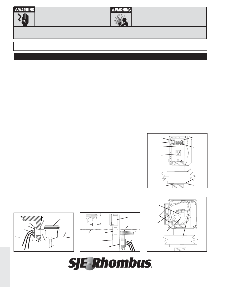
1. Determine where the junction box will
be mounted on the riser. Mount the
junction box so the base of the en-
closure will be at grade once back-
filled as shown in Figure A.
NOTE: Bottom mounting to the 3/4”
terminal adapter may be preferred
in some instances as shown in
Figure B.
2. Access the riser by providing a 2 3/8”
access hole through the riser.
3. Place the 6” threaded conduit into the
terminal adapter that is already
installed in the junction box. Slip one
PVC washer over the conduit and
slide the conduit through the riser
wall as shown in Figure C.
4. After installation through the riser, slip
the 1/2” gasket and the second PVC
washer over the conduit. Determine if
the threads provided will be adequate
to tighten the assembly to the riser. If
threading is not adequate, remove the
assembly and shorten the conduit
until threading is adequate as shown
in Figure C. NOTE: The 1/2” gasket
should compress approximately
1/4” when lock nut is tightened.
5. Repeat steps 3 and 4 until desired
length is achieved. With PVC solvent,
weld the conduit into the terminal
adapter.
6. Mount the 3/4” terminal adapter to the
bottom of the junction box with the O-
ring and lock nut provided. A 1 1/16”
hole should be provided for the
adapter.
7. Mount the assembly through the riser
as described in steps 3 and 4. Using
the 2” lock nut, compress the gasket
and riser to secure the junction box.
8. Remove the backplate assembly from
the enclosure. Bring the wiring for the
pump power and alarm junction through
the 3/4” terminal adapter. Connect the
conductors for the pump to the terminal
block; connect N (neutral) to position 1,
and L1 (line) to position 2. Connect L2
to position 1 for 230 VAC installations.
NOTE: Overload protection, branch
circuit protection and main
disconnect provided by others.
Connect the conductors for the alarm
circuit to positions 3 and 4 as shown in
Figures C and D. Place the backplate
assembly back into the enclosure.
NOTE: If an alarm system is not
used, plug the third open position
in the cord seal with the PVC plug
provided.
9. Pass the piggy-back plug, pump plug
and alarm float cables through the 2”
conduit.
10. With the three position cord seal, route
the three cables through the seal,
leaving approximately 8” of cable to
work with. Insert the cord seal into the
panel terminal adapter and tighten the
hex nut until adequate strain relief is
achieved.
11. Gather all ground wires, including
grounding conductor on the cord seal,
and washer. Route and secure to
ground terminal as shown in Figures C
and D.
INSTALL INSTRUCTIONS
INSTALLING THE JB PLUGGER JUNCTION BOX
For detailed specifications on this product, or for the complete line of SJE-Rhombus
®
panel, alarm, and switch products, visit our web-site at www.sjerhombus.com.
Figure D
pump plug
piggyback
plug
alarm float
switch
to alarm
panel
cable
coiling
detail
Figure C
ground
to alarm
panel
alarm
float
terminal
adapter
riser wall
lock nut
PVC
washer
PVC washer
cord
seal
pump
power
1 2 3 4
N L1
gasket
pump
float
switch
receptacle
grade
level
Figure A
riser
JB Plugger
conduit for electrical
(not included)
pump &
switch
cables
PVC washer
PVC washer
gasket
3/4” terminal
adapter
lock
nut
terminal
adapter
Figure B
conduit for
electrical
(not included)
LB conduit box
(not included)
spacer for lip
on riser lid
(not included)
grade
level
JB
Plugger
riser
pump &
switch cables
3”
2 1/16”
3/4” adapter location
12. Connect the conductors from the
alarm float switch to positions 3 and 4.
Coil remaining cable into the junction
box as shown in Figures C and D.
13. Seal the 3/4” terminal adapter with a
conduit sealing compound.
14. Plug the piggy-back plug and pump
plug into the receptacle as shown in
Figure D.
15. Secure the junction box cover using
the two preinstalled screws.
16. Turn on power.
17. Check the installation by manually
tipping the floats on the pump and then
the alarm float.
18. Test the unit periodically to insure
proper operation.
torque to
45 in-lbs
torque to
7 in-lbs
ELECTRICAL SHOCK HAZARD
Disconnect power before installing or servicing this
product. A qualified service person must install and
service this product according to applicable electrical
and plumbing codes.
EXPLOSION OR FIRE HAZARD
Do not use this product with flammable liquids.
Do not install in hazardous locations as defined by
National Electrical Code, ANSI/NFPA 70.
Failure to follow these precautions could result in serious injury or death. Replace product immediately if switch cable becomes damaged
or severed. Keep these instructions with warranty after installation. This product must be installed in accordance with National Electric Code,
ANSI/NFPA 70 so as to prevent moisture from entering or accumulating within boxes, conduit bodies, fittings, float housing, or cable.
112