Liberty Pumps LSGX202-RE User Manual
Page 6
©Copyright 2012 Liberty Pumps Inc. All rights reserved
- 6 -
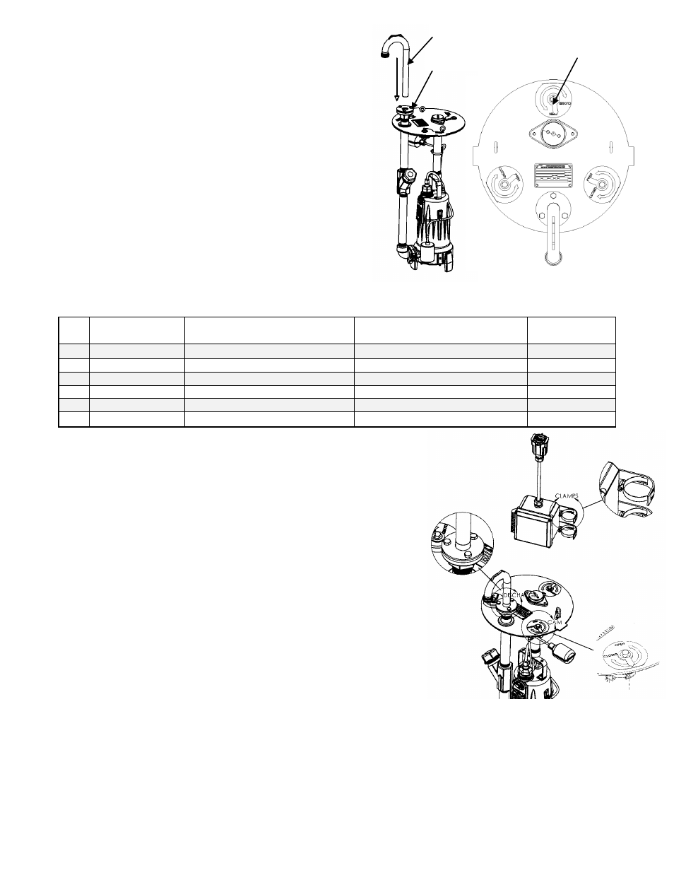
Discharge elbow
Discharge flange
Rotating cover
cam-locks
3-5 INSTALLING THE RE/REX CORE
1. Apply gasket tape to the under or bottom side of the cover at
the perimeter.
2. Adjust the discharge elbow’s height by sliding it up or down in
the discharge flange - matching that of the unit which was
removed. DO NOT fully tighten the three bolts on the discharge
flange yet. The height of the discharge elbow might need to be
slightly adjusted after the unit is assembled into the pit.
3. Located on the cover are three rotating cam-locks which are
used to secure the unit. The cam-lock must be orientated such
that the pointer aligns with the “OPEN” mark before lowering the
unit into the pit.
4. Float switches must be positioned so that they will be free of
any objects in the tank or tank walls. If adjustments are made to
either one, make sure that floats will activate properly.
Specifically, confirm that the alarm float activates before hitting
top cover.
5. Although the Liberty Pumps RE/REX models come equipped with 6-pin connectors that mate perfectly with existing
control hardware, the following table may be used for troubleshooting, repair, or custom installation purposes.
6. Lubricate the triple O-ring seal on the discharge elbow to ease installation of elbow into
receiver. With what? Is grease packet included?
7. Using the lifting rope, lower the grinder assembly into the basin. Align the cover tabs to the
mating tank slots, and discharge elbow to the receiver/ball valve. The unit should come to
rest squarely on the tank flange.
8. The three cam-locks for the cover should now be secured by rotating the
3/8” hex bolts (9/16 SOCKET) clockwise to the “CLOSED” position. The
cam-locks will wedge under the tank flange securing the cover.
9. Press downward on the discharge elbow such that it seats fully in the ball
valve’s receiver. Tighten the three 3/8 bolts (9/16 SOCKET) on the discharge
flange. This will compress the rubber ring and seal the unit.
10. Open the valve so that the handle/ latch encompasses the discharge elbow. If
problems exist with opening the valve, adjustments can be made to the height of the
discharge elbow by loosening the three screws on the discharge flange and raising
or lowering the height as needed. Be sure to retighten the screws after adjustment.
11. The control box is designed to be mounted higher in the pit’s access chamber and
above a potential flood level should a power outage occur. 8 feet of cable is
provided to the control box to accommodate various pit heights. Mount the control
box as high as possible to the existing vent pipe using the supplied brackets and hose clamps. The brackets must first be
screwed onto the control panel, then install the hose clamps through the slotted openings on the bracket.
12. The 6-pin electrical connector (either round or square) will mate up with the existing E/one® plug in the pit. No splicing is
required. Simply connect the plugs together and ensure they are fully engaged. Note: The manual over-ride switch will
remain operational in the original equipment E/one® panel.
13. An auxiliary or second nameplate is provided and should be fastened to the existing control panel to properly identify the
new pump.
PIN
Function
GP200/GP2000
(square connector body)
Extreme D-Series
(round connector body)
Liberty
RE/REX
1
Manual Run
Red
Brown
Red
2
L1
Black
Red
Black
3
L2
White
Black
Yellow
4
Ground
Green
Green/Yellow
Brown
5
Alarm Feed
Orange
Yellow
Orange
6
Alarm Return
Blue
Blue
Blue