Wiring diagram – Gorman-Rupp Pumps S3B65-E6 460/3 861279 thru 1217130 User Manual
Page 23
OM−04410
CONTROL BOXES
PAGE B − 16
INSTALLATION
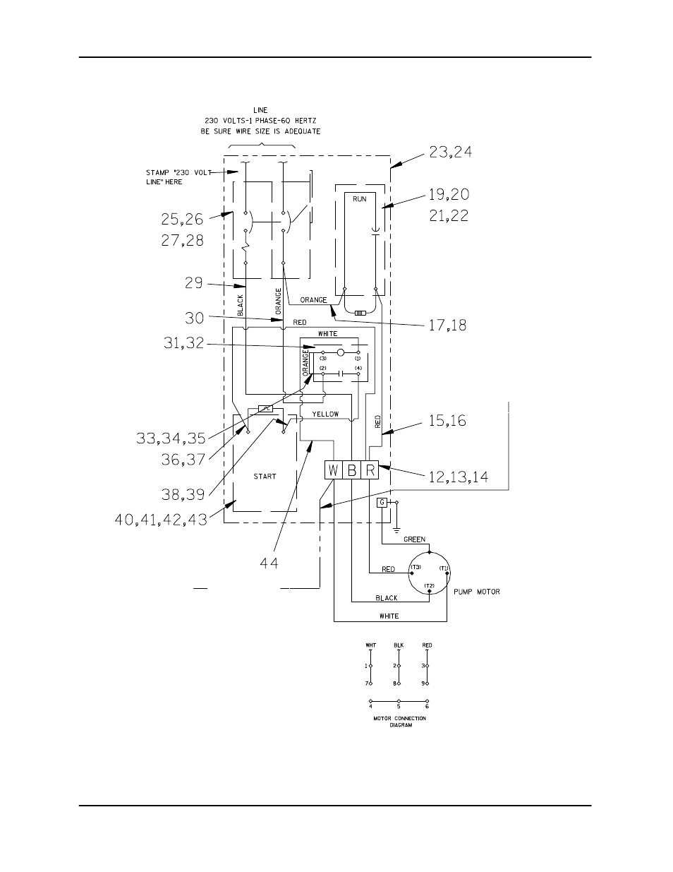
WIRING DIAGRAM
OPTIONAL
ORANGE LIQUID
LEVEL CONTROL
LEAD
WHEN USING OPTIONAL LIQUID LEV-
EL CONTROL (P/N 47631−070) CUT
THE TERMINAL OFF OF THE ORANGE
LIQUID LEVEL CONTROL CABLE AND
CONNECT THE ORANGE LEAD TO
THE PUMP CONTROL TERMINAL
BLOCK ‘W’.
NOTE
Figure B−13. Control Box 47631−126 Pictorial Wiring Diagram
For specific control box data information, refer to
the chart at the end of this section.
This manual is related to the following products: