Gorman-Rupp Pumps 82D3-B 274955 and up User Manual
Page 24
OM−00806
80 SERIES
MAINTENANCE & REPAIR
PAGE E − 5
Pump Casing and Wear Plate Removal
To service the wear plate (20), remove the nuts (18)
securing the pump casing to the seal plate (6) and
pedestal (14). Separate the pump casing and re-
move the gasket set (19).
Inspect the wear plate for scoring or excessive
wear. To remove the wear plate, disengage the
hardware (21, 22, 26 and 27). Pull the wear plate
out of the pump casing.
Impeller Removal
Immobilize the impeller by wedging a block wood
between the vanes. If removed, install the shaft
key (10). Install a lathe dog on the drive end of the
shaft (11) with the V" notch positioned over the
shaft keyway.
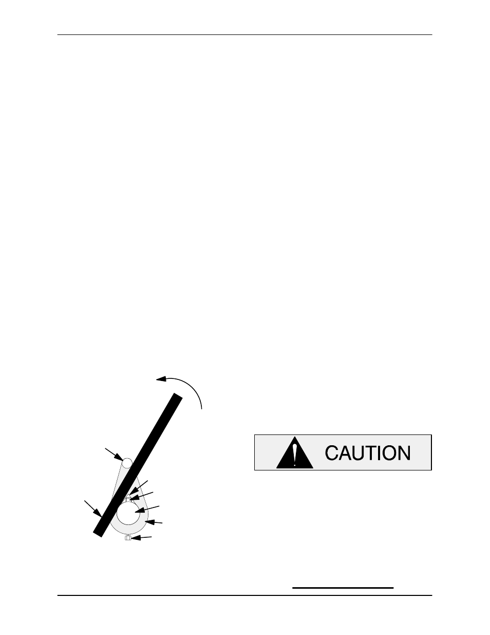
With the impeller rotation still blocked, strike the
lathe dog sharply in a counterclockwise direction
(when facing the drive end of the shaft). The impel-
ler may also be loosened by using a long piece of
heavy bar stock to pry against the arm of the lathe
dog in a counterclockwise direction (when facing
the drive end of the shaft) as shown in Figure 2.
Use caution not to damage the shaft or keyway.
When the impeller breaks loose, remove the lathe
dog and wood block and unscrew the impeller
from the shaft.
Turn
Counterclockwise
Lathe Dog Arm
V" Notch
Shaft Key
Impeller Shaft
Lathe Dog
Setscrew
Heavy
Bar Stock
Figure 2. Loosening Impeller
Unscrew the impeller from the shaft. Use caution
when removing the impeller; tension on the seal
spring will be released as the impeller is un-
screwed.
Inspect the impeller and replace it if cracked or
badly worn. Slide the impeller adjusting shims (4)
off the impeller shaft. Tie and tag the shims, or
measure and record their thickness for ease of
reassembly.
Seal Removal and Disassembly
Carefully slide the shaft sleeve (5) and rotating por-
tion of the seal off the shaft as a unit. Apply oil to the
sleeve and work it up under the rubber bellows.
Slide the rotating portion of the seal off the sleeve.
Carefully slide the seal plate (6) and stationary por-
tion of the seal off the shaft (11) as a unit.
Position the seal plate on a flat surface with the im-
peller side down. Use a suitably sized dowel to
press the stationary seat and O-ring out of the seal
plate from the back side.
If no further disassembly is required, see Seal
Reassembly and Installation.
Shaft And Bearing Removal And Disassembly
When the pump is properly operated and main-
tained, the pedestal should not require disassem-
bly. Disassemble the shaft and bearings only
when there is evidence of wear or damage.
Shaft and bearing disassembly in the field
is not recommended. These operations
should be performed only in a properly
equipped shop by qualified personnel.
NOTE
There are no provisions for draining the grease
from the pedestal. Place a drip pan under the ped-
estal before removing the shaft and bearings.