Gorman-Rupp Pumps 83B2-B 1063841 and up User Manual
Page 29
80 SERIES
OM−00868
MAINTENANCE & REPAIR
PAGE E − 8
Inspect the seal components for wear, scoring,
grooves, and other damage that might cause leak-
age. Clean and polish the shaft sleeve, or replace it
if there are nicks or cuts on either end. If any com-
ponents are worn, replace the complete seal;
never mix old and new seal parts.
If a replacement seal is being used, remove it from
the container and inspect the precision finished
faces to ensure that they are free of any foreign
matter.
To ease installation of the seal, lubricate the shaft
sleeve, packing rings and seal liner with water or a
very small amount of oil, and apply a drop of light
lubricating oil on the finished faces. Assemble the
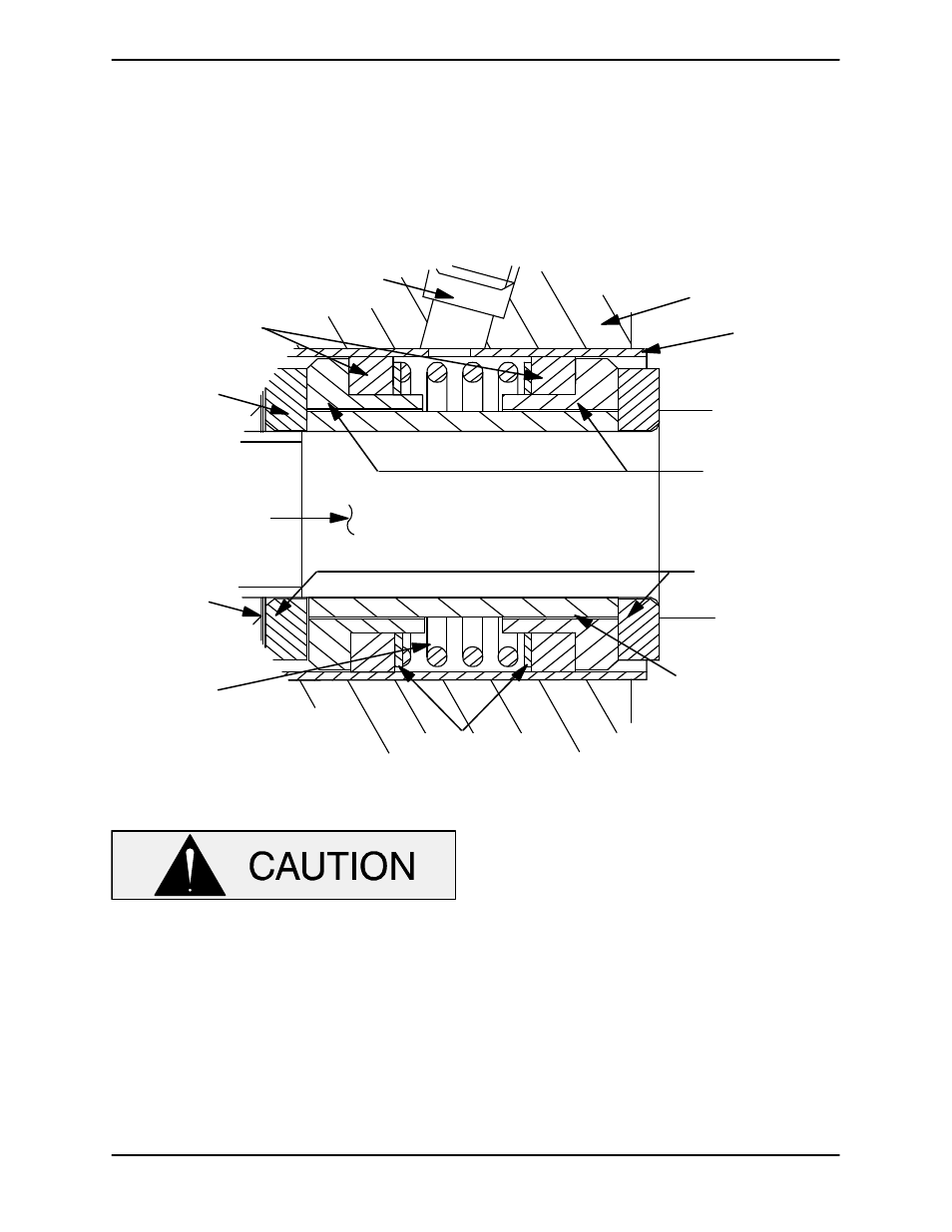
seal as follows, (see Figure 3).
IMPELLER SHAFT
SEAL
PLATE
SEAL
LINER
IMPELLER
IMPEL-
LER
SHIMS
GREASE CUP
PIPING
SEAL
SPACER
SLEEVE
PACKING
RINGS
STATIONARY
SEAL SEATS
ROTATING
ELEMENTS
SPRING
STATIONARY
WASHERS
Figure 3. 25284−951 Seal Assembly
This seal is not designed for operation at
temperatures above 110
_F (43_C). Do not
use at higher operating temperatures.
Inspect the seal plate (36), seal liner (15) and the
impeller shaft for burrs or sharp corners, and re-
move any that exist. Replace the seal liner if wear or
grooves exist which could cause leakage or dam-
age to the seal packing rings. To replace the seal
liner, position the seal plate on the bed of an arbor
(or hydraulic) press, and use a new sleeve to force
the old one out. After the new liner is properly in-
stalled, a 1/4-inch (6,4 mm) diameter hole must
drilled through it to permit the flow of lubricant to
the seal assembly. Be careful to center the drill in
the threaded grease pipe hole and not damage the
threads. Deburr the hole from the inside of the seal
liner after drilling.
Slide the seal plate and gasket (37) onto the shaft
until fully seated against the pedestal (20). Align
the threaded seal lubricant hole with the pedestal
opening, and temporarily secure the seal plate to
the pedestal with three capscrews (3/8−16 UNC x
1−1/2 inch long, not supplied) and nuts.
Position the inboard rotating element on the shaft
with the chamfered side facing away from the im-