Lubrication – Gorman-Rupp Pumps 84B2-B 667409 and up User Manual
Page 31
80 SERIES
OM-00930
MAINTENANCE & REPAIR
PAGE E - 10
Check the operation of the check valve to ensure
proper seating and free movement.
Final Pump Reassembly
Be sure all hardware and drain plugs are tight, and
that the pump is secure to the base and power
source.
Install the suction and discharge lines and open all
valves. Make certain that all piping connections are
tight, and that the weight of the lines is indepen
dently supported and secure.
Before starting the pump, fill the pump casing with
clean liquid. Apply “Never‐Seez” or equivalent
compound to the fill plug (8). Reinstall and tighten
the fill plug.
Refer to OPERATION, Section C, before putting
the pump back into service.
LUBRICATION
Seal Assembly
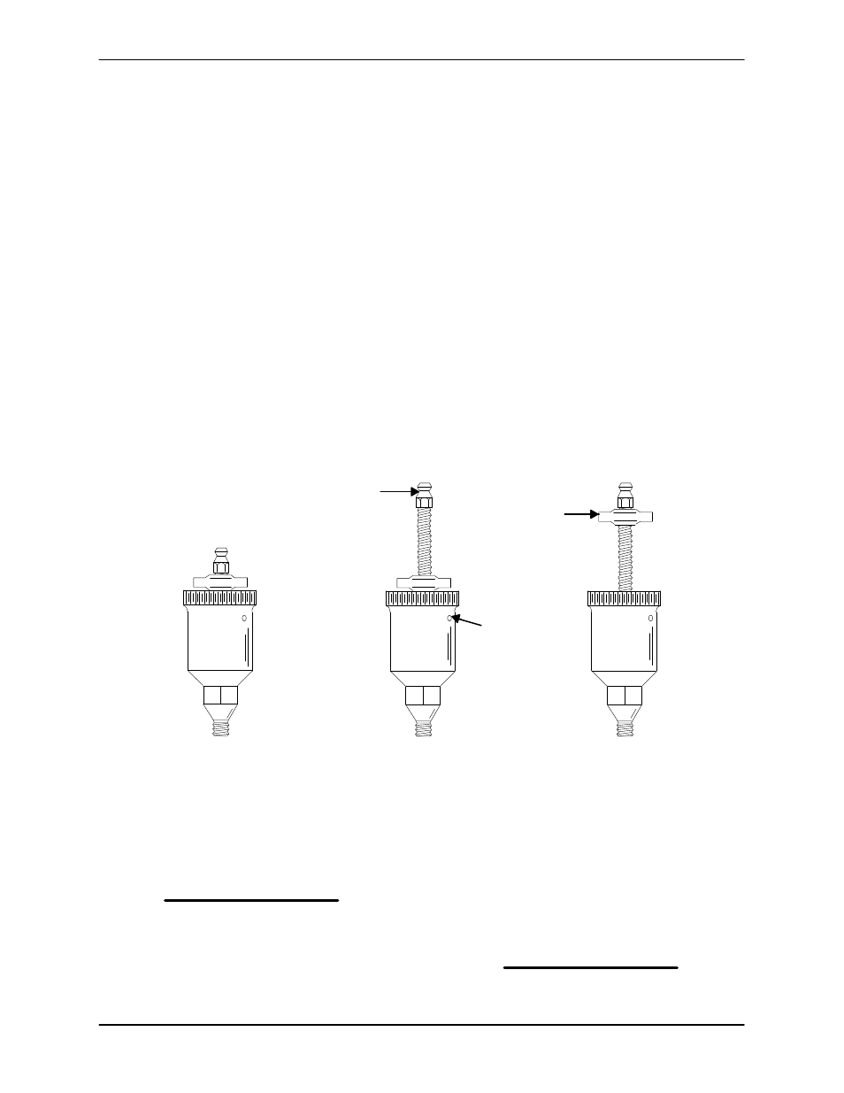
Fill the grease cup (11) through the grease fitting
with No. 2 lithium base grease until grease es
capes from the relief hole. Turn the grease cup arm
counterclockwise until it is at the top of the stem;
this will release the spring to apply grease to the
seal (see Figure 4).
GREASE
FITTING
CROSS
ARM
POSITION
WHEN
EMPTY
POSITION
FOR
FILLING
POSITION
WHEN
IN USE
RELIEF
HOLE
Figure 4. Automatic Lubricating Grease Cup
NOTE
Some smoking and leakage may occur after instal
ling a new seal assembly. This should stop after the
pump has run a while and the lapped seal faces
have seated in.
Bearings
The pedestal was fully lubricated when shipped
from the factory. Check the oil level regularly
through the sight gauge (31) and maintain it at the
middle of the gauge. When lubrication is required,
add SAE No. 30 non‐detergent oil through the hole
for the air vent (19). Do not over‐lubricate. Over‐lu
brication can cause the bearings to over‐heat, re
sulting in premature bearing failure.
NOTE
The white reflector in the sight gauge must be posi
tioned horizontally to provide proper drainage.
Under normal conditions, change the oil each
5000 hours or once each year, more frequently if