Gorman-Rupp Pumps 112D60-B 1288322 and up User Manual
Page 32
OM−01830
10 SERIES
MAINTENANCE & REPAIR
PAGE E − 9
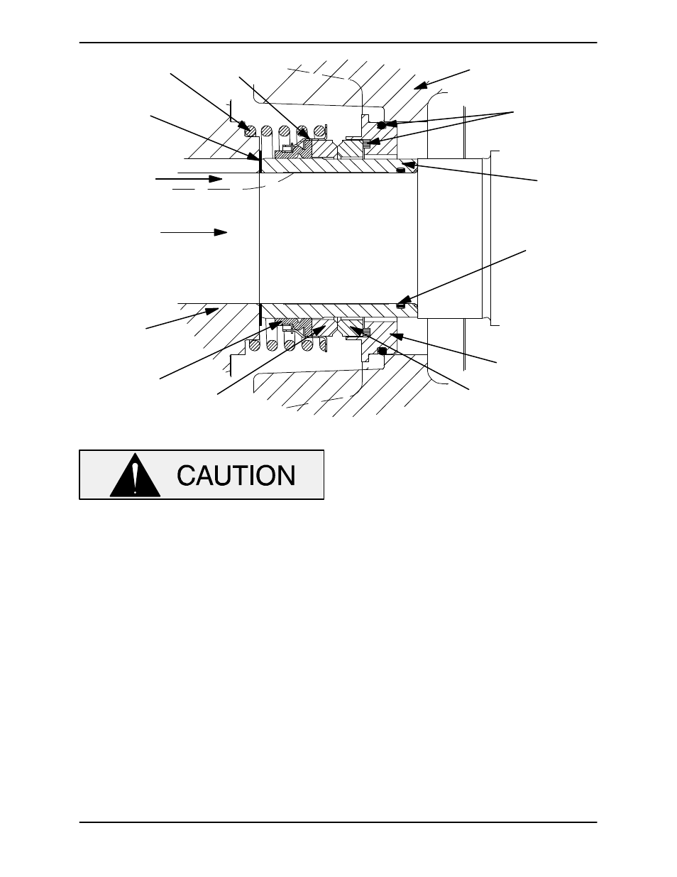
IMPELLER
SHAFT
IMPELLER
SHAFT
SLEEVE
RETAINER
ROTATING
ELEMENT
STATIONARY
ELEMENT
SPRING
SEAL PLATE
STATIONARY
SEAT
SHAFT
SLEEVE
O-RING
O-RINGS
BELLOWS
IMPELLER
SHIMS
SHAFT
KEY
Figure E−2. 46512−259 Seal Assembly
This seal is not designed for operation at
temperatures above 160
_F (71_C). Do not
use at higher operating temperatures.
Lubricate the O-rings (22 and 52) with a small
amount of grease and install them on the seal plate
(55).
Position the seal plate on a flat surface with the im-
peller side up. Press the stationary subassembly
(consisting of the stationary seat, O-rings and sta-
tionary element) into the seal plate until the station-
ary seat bottoms against the seal plate bore.
Slide the seal plate onto the shaft and secure it to
the pedestal with the hardware (24 and 25).
Lubricate and install the O-ring in the groove in the
I.D. of the shaft sleeve (30). Lubricate the shaft
sleeve and slide the rotating subassembly (con-
sisting of the rotating element, retainer and bel-
lows) onto the sleeve until the rotating element is
just flush with the chamfered end of the shaft.
Slide the sleeve and rotating subassembly onto
the shaft until the seal faces contact. Use caution
to ensure that the shaft sleeve O-ring is not cut or
damaged on the impeller keyway. Continue to
push the sleeve through the seal until it bottoms
against the shaft shoulder. Install the seal spring.
Lubricate the seal assembly as indicated in
LUBRICATION, after the impeller has been in-
stalled.
Impeller Installation And Adjustment
Inspect the impeller, and replace it if cracked or
badly worn. Install the same thickness of impeller
adjusting shims as previously removed, and install
the impeller key (80). Apply a thin, uniform coat of
Never-Seez" or equivalent compound to the shaft
area under the impeller and press the impeller onto
the shaft until fully seated. Make sure the seal
spring is squarely seated over the step on the back
of the impeller.
A clearance of .010 to .020 inch (0,25 to 0,51 mm)
is required between the impeller and seal plate to