Gorman-Rupp Pumps 11 1/2A65-B 776101 and up User Manual
Page 32
OM-02154
10 SERIES
MAINTENANCE & REPAIR
PAGE E - 9
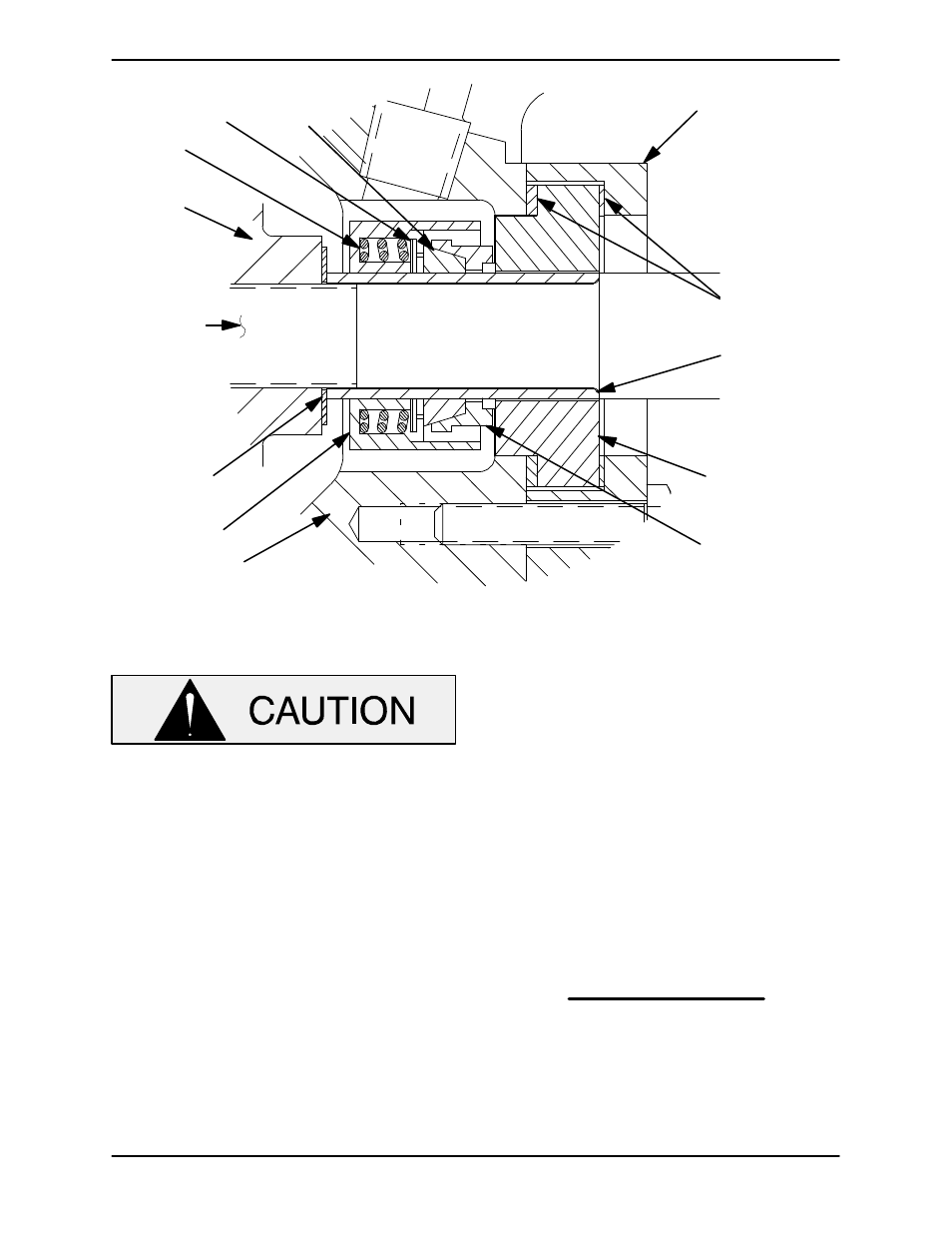
SEAL CLAMP
IMPELLER
SHAFT
STATIONARY
SEAT
ROTATING
ELEMENT
IMPELLER
SHIMS
IMPELLER
SPRING
SHAFT
SLEEVE
RETAINER
GASKETS
SEALING
WEDGE
DISC
SEAL PLATE
Figure 3. Seal Assembly
This seal is not designed for operation at
temperatures above 160
_F (71_C). Do not
use at higher operating temperatures.
Position the seal plate (34) on a flat surface with the
impeller side down. Assemble the stationary seat
and gaskets in the seal clamp (31) with the white
gasket toward the seal cavity side of the stationary
seat. Secure the seal cap and stationary seal com
ponents to the seal plate with the capscrews (30).
Slide the seal plate over the shaft until fully seated
against the pedestal (16). Be careful not to dam
age the seal stationary seat on the shaft threads.
Align the pipe plug (12) with the pedestal opening
and temporarily secure the seal plate to the pedes
tal using two capscrews and nuts (3/8‐16 UNC X 1
1/2 inch long, not supplied).
Slide the rotating portion of the seal onto the lubri
cated shaft sleeve to the dimension (or scribed
line) noted during disassembly.
NOTE
The designed working length of the seal is 0.875
inch (22,2 mm) from the face of the stationary seat
to the back of the seal retainer, when the seal
springs are compressed. If a new sleeve is being
used, slide the sleeve onto the shaft until it seats
against the shaft shoulder, then measure and mark
the sleeve 0.875 inch (22,2 mm) from the stationary
face. Remove the sleeve from the shaft and slide the
rotating portion of the seal onto the lubricated shaft
sleeve to this mark.
Secure the stationary portion of the seal to the
sleeve by tightening the setscrews in the seal re
tainer.
Slide the sleeve and rotating portion of the seal
onto the shaft until the seal elements contact.