Lubrication – Gorman-Rupp Pumps 16A2-4045T 1514795 and up User Manual
Page 37
OM-06540
10 SERIES
MAINTENANCE & REPAIR
PAGE E - 17
Clean any scale or debris from the contacting sur
faces in the pump casing that might interfere or
prevent a good seal with the back cover. Replace
the back cover gasket (57) and slide the back
cover assembly into the pump casing. Be sure the
wear plate does not bind against the impeller.
NOTE
To ease future disassembly, apply a film of grease
or `Never‐Seez' on the back cover shoulder, or any
surface which contacts the pump casing. This ac
tion will reduce rust and scale build‐up.
Secure the back cover assembly by tightening the
cover clamp screw (58) against the clamp bar (59).
Do not over‐tighten the clamp screw; it should be
just tight enough to ensure a good seal at the back
cover shoulder.
Final Pump Assembly
Install any leveling shims used under the pump
casing mounting feet and secure the casing to the
base with the previously removed hardware. Be
sure the pump is secured to the base and engine.
Install the suction and discharge lines and open all
valves. Make certain that all piping connections are
tight, properly supported and secure.
Be sure the pump end and engine have been
properly lubricated, see LUBRICATION.
(Figure 3)
Remove the fill cover assembly (12). Fill the pump
casing with clean liquid. Reinstall the fill cover plate
and gasket (16), and tighten the cover.
Refer to OPERATION, Section C, and start the
pump.
LUBRICATION
Seal Assembly
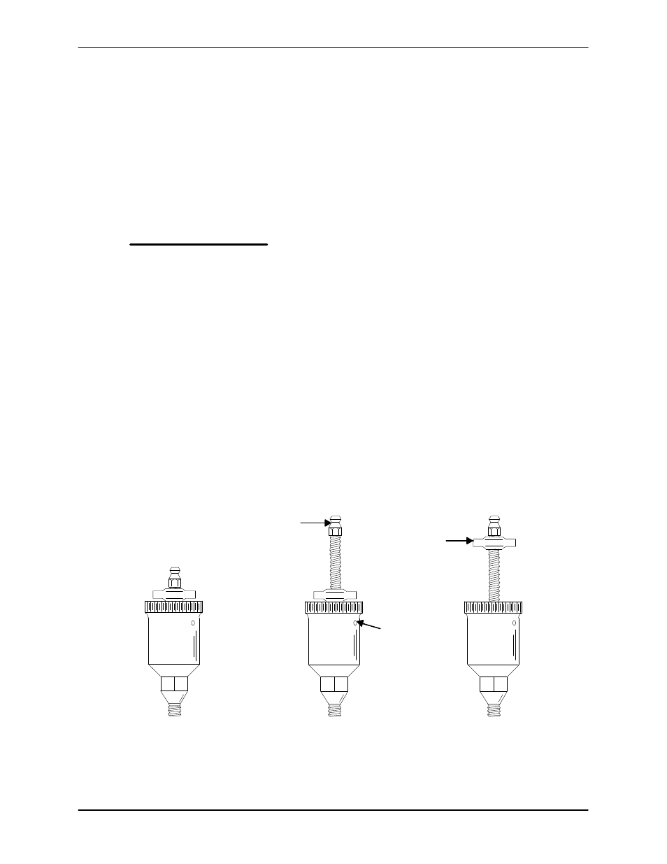
(Figure 7)
Fill the grease cup (27) through the grease fitting
with No. 2 lithium base grease until grease es
capes from the relief hole. Turn the grease cup arm
counterclockwise until it is at the top of the stem;
this will release the spring to apply grease to the
seal (see Figure 7).
GREASE
FITTING
CROSS
ARM
POSITION
WHEN
EMPTY
POSITION
FOR
FILLING
POSITION
WHEN
IN USE
RELIEF
HOLE
Figure 7. Automatic Lubricating Grease Cup
Bearings
(Figure 3)
The intermediate was fully lubricated when
shipped from the factory. Check the oil level regu
larly through the sight gauge (41)
and maintain it at
the middle of the gauge. When lubrication is re
quired, add SAE No. 30 non‐detergent oil through