Gorman-Rupp Pumps U6B65S-B 1289655 and up User Manual
Page 35
OM-05670
SUPER U SERIES
MAINTENANCE & REPAIR
PAGE E - 12
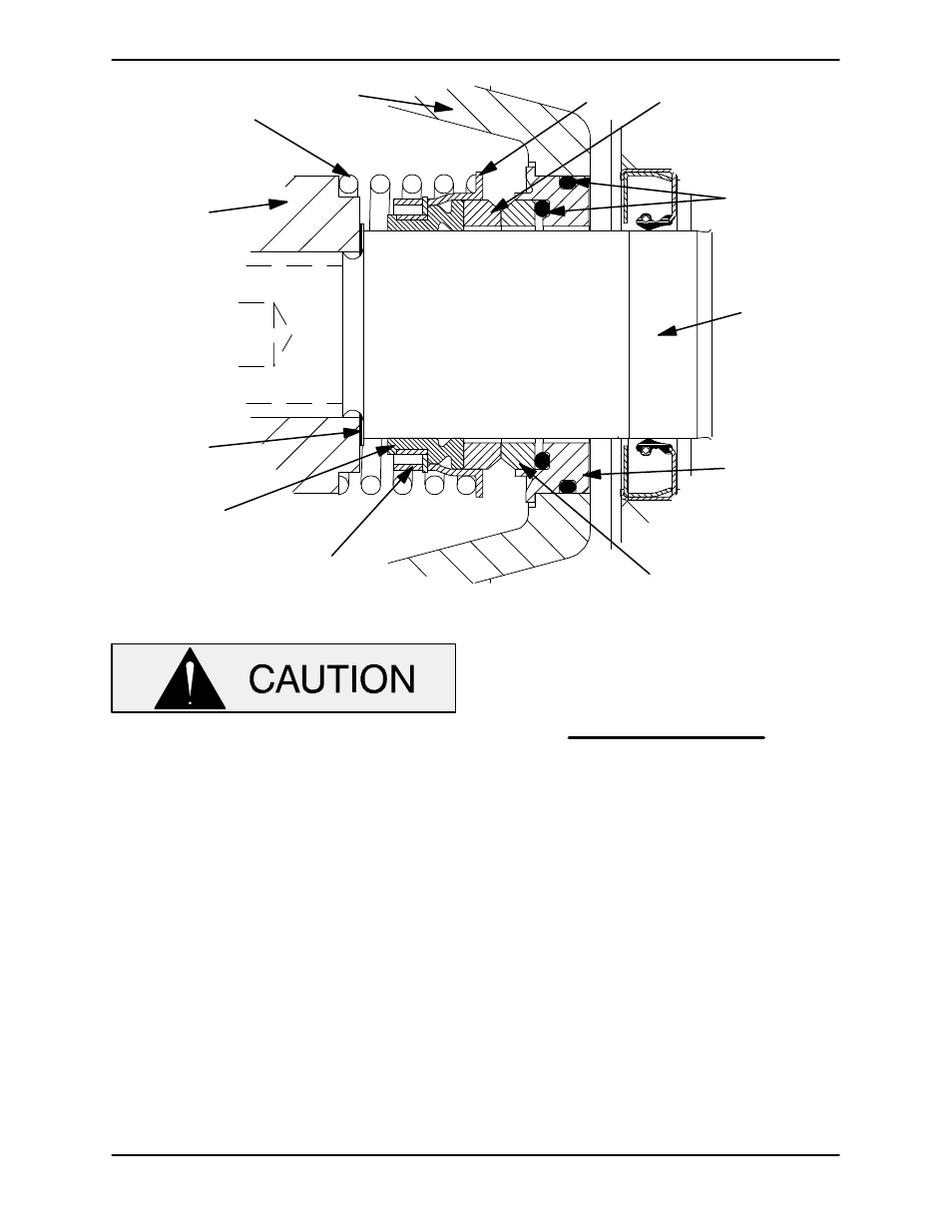
IMPELLER
SHAFT
STATIONARY
SEAT
STATIONARY
ELEMENT
DRIVE BAND
BELLOWS
IMPELLER
SHIMS
SPRING
ROTATING
ELEMENT
SEAL
PLATE
O‐RINGS
IMPELLER
RETAINER
Figure 6. 46512-192 Cartridge Seal Assembly
This seal is not designed for operation at
temperatures above 160
_ F (71_ C). Do
not use at higher operating temperatures.
Lubricate the stationary seat O‐rings with water or
light oil, and install them in the stationary seat. In
stall the stationary seal element in the stationary
seat. Press this stationary subassembly into the
front of the seal plate until it seats squarely against
the bore shoulder.
Install the seal plate gasket (3). Position the seal
plate (2) and stationary seat over the shaft, and se
cure it to the bearing housing with the hardware (4
and 5). Be careful not to damage the stationary
element on the shaft threads.
NOTE
It is recommended that a tapered sleeve be
installed over the threads of the impeller shaft to
ease installation of the rotating seal components.
Lubricate the shaft (24) with a small amount of light
oil and slide the rotating subassembly (consisting
of rotating element, bellows and retainer), onto the
shaft until the seal faces contact.
Install the seal spring. Lubricate the seal as indi
cated in LUBRICATION after the impeller is in
stalled.
Impeller Installation and Adjustment.
(Figure 2)
Inspect the impeller, and replace it if cracked or
badly worn. Inspect the impeller and shaft threads
for dirt or damage, and clean or dress the threads
as required.