Gorman-Rupp Pumps V3B60-B 1368385 and up User Manual
Page 33
OM−06015
ULTRA V SERIES
MAINTENANCE & REPAIR
PAGE E − 11
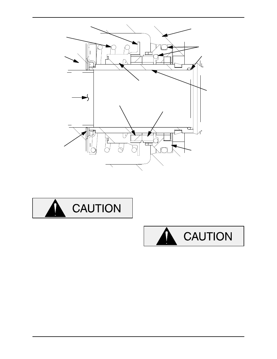
SEAL PLATE
O-RINGS
IMPELLER
SHAFT
STATIONARY
SEAT
STATIONARY
ELEMENT
ROTATING
ELEMENT
BELLOWS
IMPELLER
SHIMS
IMPELLER
SPRING
RETAINER
SEAL SLEEVE
O-RING
INTEGRAL
SHAFT
SLEEVE
Figure 5. Cartridge Seal Assembly
This seal is not designed for operation at
temperatures above 160
_
F (71
_
C). Do not
use at higher operating temperatures.
If the seal plate was removed, install the seal plate
gasket (5). Position the seal plate over the shaft
and secure it to the bearing housing with the hard-
ware (7 and 8).
To prevent damaging the shaft sleeve O-ring (25)
on the shaft threads, stretch the O-ring over a piece
of plastic tubing that the I.D. is a little larger than the
O.D. of the shaft. Slide the tube over the shaft
threads, then slide the O-ring off the tube and onto
the shaft. Remove the tube, and continue to slide
the O-ring down the shaft until it seats against the
shaft shoulder.
When installing a new cartridge seal assembly,
remove the seal from the container, and remove
the mylar storage tabs, if so equipped, from be-
tween the seal faces.
Some cartridge seal assemblies are
equipped with mylar storage tabs between
the seal faces. These storage tabs must be
removed before installing the seal.
Lubricate the external stationary seat O-ring with
light oil. Slide the seal assembly onto the shaft until
the external stationary seat O-ring engages the
bore in the seal plate.
Clean and inspect the impeller as described in Im-
peller Installation and Adjustment. Install the full
set of impeller shims (2) provided with the seal, and
screw the impeller onto the shaft until it is seated
against the seal (see Figure 6).