Gorman-Rupp Pumps VS6A60-B 1352521 and up User Manual
Page 14
OM-06014
ULTRA V SERIES
PAGE B - 7
INSTALLATION
ard 1‐inch NPT fitting, or the Air Release Valve may
be installed in a spool flange between the two dis
charge check valves.
Connect the valve outlet to a bleed line which
slopes back to the wet well or sump. The bleed line
must be the same size as the outlet opening or lar
ger, depending on which Air Release Valve is being
used. If piping is used for the bleed line, avoid the
use of elbows whenever possible.
NOTE
For multiple pump installations, it is recommended
that each Air Release Valve be fitted with an inde
pendent bleeder line directed back to the wet well.
If multiple Air Release Valves are installed in a sys
tem, do not direct bleeder lines to a common mani
fold pipe. Contact your Gorman‐Rupp distributor or
the Gorman‐Rupp Company for information about
installation of an Automatic Air Release Valve for
your specific application.
DRIVE ARRANGEMENTS
Special consideration must be given to drive ar
rangements for staged pumping applications.
Since pump installations are seldom identical, this
section provides some general recommendations
for selecting drive arrangements for staged
pumps. Consult the factory for information regard
ing your specific application.
Dual Motor Drives
It is recommended that each pump be directly driv
en by its own electric motor, either through coup
lings (see Figure 3) or a belt arrangement (see Fig
ure 4).
Each motor should be independently operated
through a reduced voltage solid state (RVSS)
starter, a variable frequency drive (VFD) or an ad
justable speed drive (ASD). In this arrangement,
the motor powering the lower stage pump should
be programmed to start first and “ramp up” to full
condition speed, then the second stage pump mo
tor should start and “ramp up” to full condition
speed. Pump motor shutdown should be pro
grammed in reverse order, with the second stage
pump motor “ramping down” before shutting off,
then the first stage pump motor “ramping down”
and shutting off. This “ramp up” and “ramp down”
configuration helps reduce inrush current on star
tup and destructive “water hammer” on both star
tup and shut down.
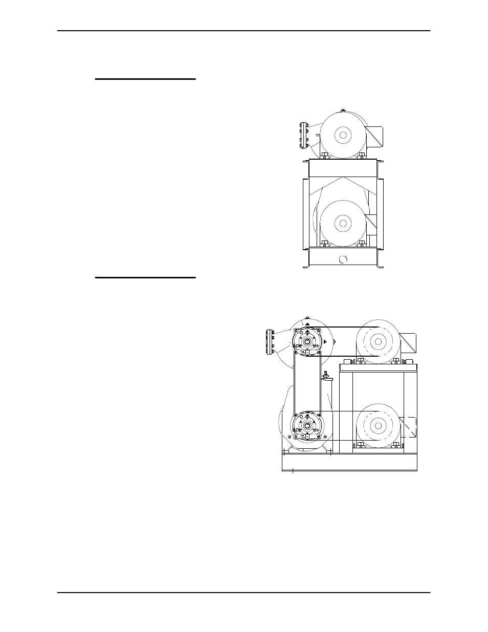
Figure 3. Recommended Dual Motor Direct
Drive Arrangement
Figure 4. Recommended Dual Motor Belt
Drive Arrangement
Single Motor Belt Drives
In staged applications where both pumps are belt
driven by a single motor (either through a syn
cronous [cog] or V‐belt configuration) certain ar
rangements must be used in order to ensure prop
er operation.