Gorman-Rupp Pumps T10A65S-6068T 1413937 and up User Manual
Page 44
OM−06198
SUPER T SERIES
MAINTENANCE & REPAIR
PAGE E − 17
If a replacement seal is being used, remove it from
the container and inspect the precision finished
faces to ensure that they are free of any foreign
matter.
To ease installation of the seal, lubricate the bel-
lows and stationary seat O-rings with water or a
very small amount of oil, and apply a drop of light
lubricating oil on the finished faces. Assemble the
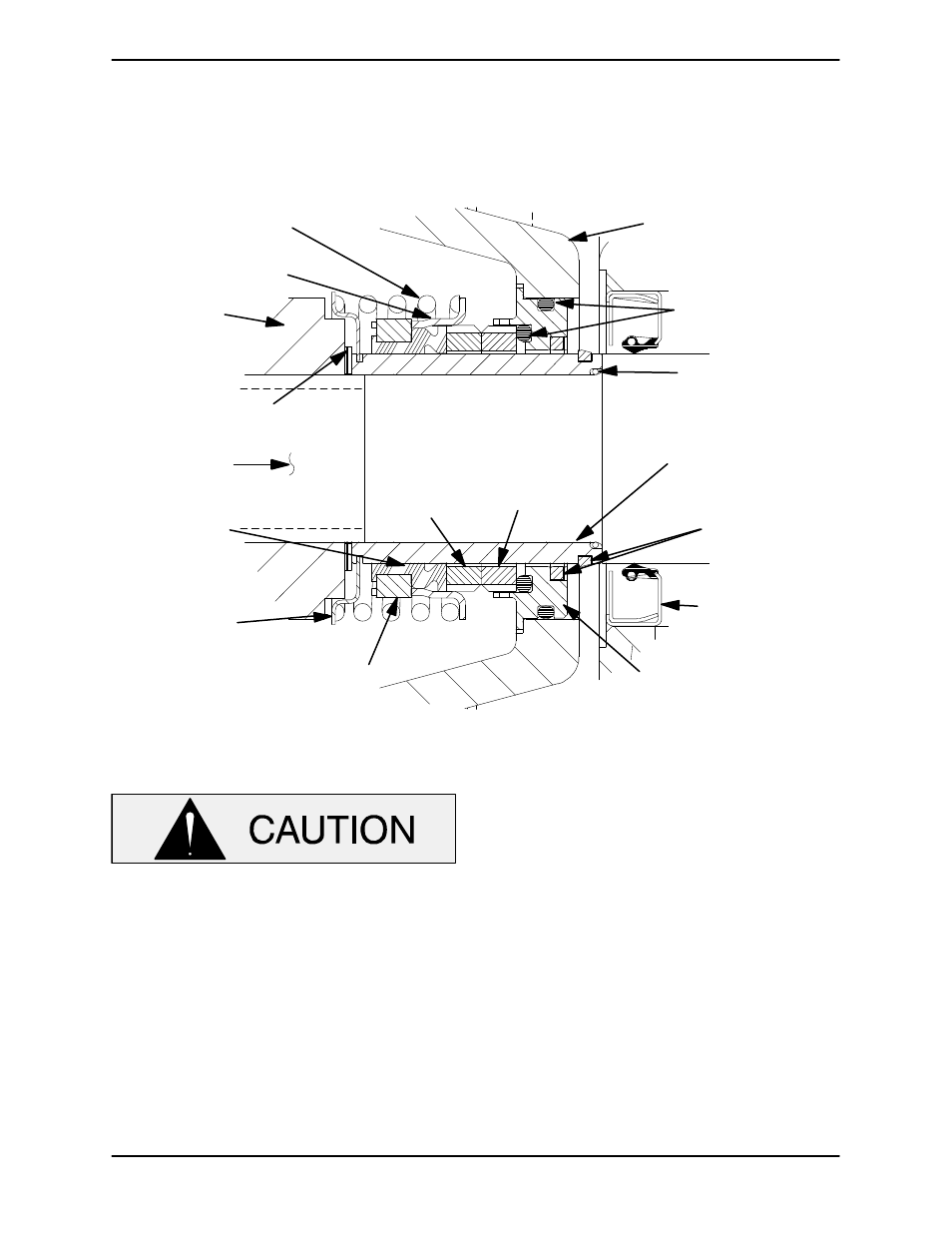
seal as follows, (see Figure 8).
SEAL PLATE
O-RINGS
IMPELLER
SHAFT
STATIONARY
SEAT
STATIONARY
ELEMENT
ROTATING
ELEMENT
DRIVE BAND
BELLOWS
IMPELLER
SHIMS
IMPELLER
SPRING
RETAINER
INTEGRAL
SHAFT
SLEEVE
SLEEVE
O-RING
SPRING
CENTERING
WASHER
SHEAR
RING
(SHEARED)
OIL SEAL
Figure 8. 46513−159 Seal Assembly
This seal is not designed for operation at
temperatures above 160
_
F (71
_
C). Do not
use at higher operating temperatures.
If the seal plate was removed, install the seal plate
gasket (4) and bearing housing O-ring (5). Lubri-
cate the O-ring with light grease. Position the seal
plate over the shaft and secure it to the bearing
housing with the hardware (6 and 7).
To prevent damaging the shaft sleeve O-ring (30)
on the shaft threads, stretch the O-ring over a piece
of tubing 1-1/2" I.D. x 1-3/4" O.D. x 2-inches long
(38 mm x 45 mm x 51 mm). Slide the tube over the
shaft threads, then slide the O-ring off the tube and
onto the shaft. Remove the tube, and continue to
slide the O-ring down the shaft until it seats against
the shaft shoulder.
When installing a new cartridge seal assembly, re-
move the seal from the container, and lubricate the
external stationary seat O-ring with light oil. Slide
the seal assembly onto the shaft until the external
stationary seat O-ring engages the bore in the seal
plate.
Clean and inspect the impeller as described in Im-
peller Installation and Adjustment. Install the full
set of impeller shims (29) provided with the seal,
and screw the impeller onto the shaft until it is
seated against the seal (see Figure 9).