Gorman-Rupp Pumps T8A60S-F6L 1278434 thru 1318430 User Manual
Page 42
OM−05517
SUPER T SERIES
MAINTENANCE & REPAIR
PAGE E − 13
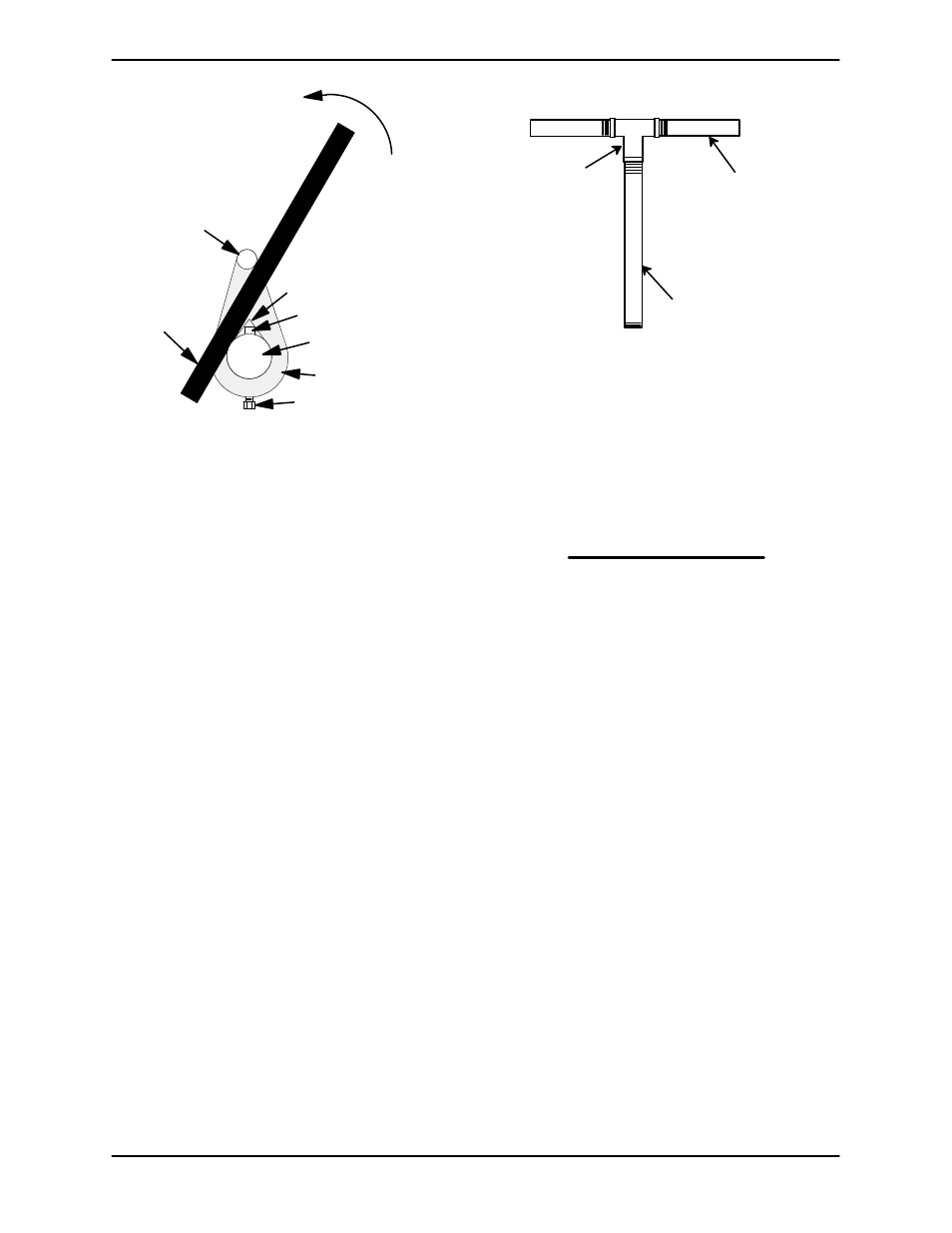
Turn
Counterclockwise
Lathe Dog Arm
V" Notch
Shaft Key
Impeller
Shaft
Lathe Dog
Setscrew
Heavy
Bar Stock
Figure 6. Loosening Impeller
Rotating Assembly Removal
(Figure 3)
Remove the outer hardware (15 and 16) from the
casing ring (14). Install three of the outer cap-
screws in the jacking holes in the casing ring, and
use them to jack the rotating assembly loose from
the pump casing.
After the rotating assembly is loosened, remove
the jacking screws from the casing ring. Remove
the inner hardware (17 and 18) and shims (13).
Separate the casing ring from the pump casing. Tie
and tag the shims for ease of reassembly.
NOTE
An optional disassembly tool is available from the
factory. If the tool is used, follow the instructions
packed with it. A similar tool may be assembled us-
ing 1/2-inch pipe (schedule 80 steel or malleable
iron) and a standard tee (see Figure 7). All threads
are 1/2-inch NPT. Do not pre-assemble the tool.
TEE
APPROX. 6 IN.
(152 MM) LONG
APPROX. 14 IN.
(356 MM) LONG
Figure 7. Rotating Assembly Tool
To install the tool, remove the vented plug (9, Figure
4) from the bearing housing, and screw the longest
length of pipe into the vent hole until fully engaged.
Install the tee, and screw the handles into the tee.
Use caution when lifting the rotating assembly to
avoid injury to personnel or damage to the assem-
bly.
Remove the bearing housing and seal plate O-
rings (32 and 33).
Impeller Removal
(Figure 4)
With the rotating assembly removed from the
pump casing, unscrew the impeller from the shaft.
Use caution when unscrewing the impeller; ten-
sion on the shaft seal spring will be released as the
impeller is removed. Inspect the impeller and re-
place if cracked or badly worn.
Remove the impeller adjusting shims (29); tie and
tag the shims, or measure and record their thick-
ness for ease of reassembly.
Seal Removal
(Figure 4)
Slide the integral shaft sleeve and rotating portion
of the seal off the shaft as a unit.
Use a pair of stiff wires with hooked ends to remove
the stationary element and seat.
An alternate method of removing the stationary
seal components is to remove the hardware (5 and