Alignment – Gorman-Rupp Pumps V6A60-D914L6 1454318 and up User Manual
Page 16
ULTRA V SERIES
OM−06295
PAGE B − 9
INSTALLATION
Consult the manual accompanying the Air Release
Valve for additional information on valve installation
and performance.
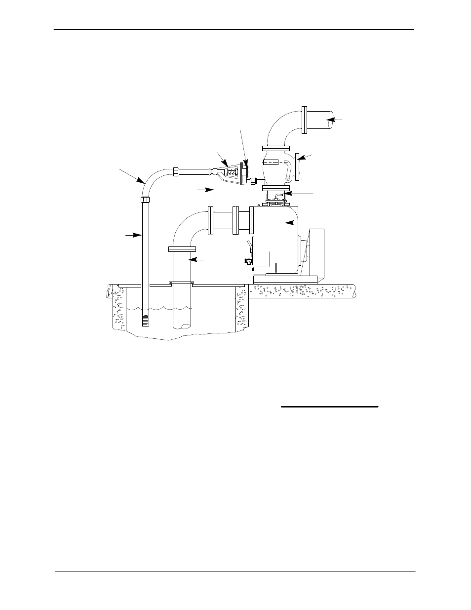
Air Release Valve Installation
The Automatic Air Release Valve must be inde-
pendently mounted in a horizontal position be-
tween the pump discharge port
and the inlet side of
the discharge check valve (see Figure 5). The inlet
opening in the Air Release Valve is equipped with
standard 1-inch NPT pipe threads.
DISCHARGE PIPE
DISCHARGE
CHECK VALVE
PUMP DISCHARGE
SELF-PRIMING
CENTRIFUGAL
PUMP
SUCTION
LINE
SUPPORT
BRACKET
CLEAN-OUT
COVER
INSTALL AIR RELEASE VALVE
IN HORIZONTAL POSITION
90
_ LONG
RADIUS
ELBOW
WET WELL
OR SUMP
BLEED LINE 1"
(25,4 MM) DIA. MIN.
(CUSTOMER FUR-
NISHED) EXTEND 6"
(152 MM) BELOW
PUMP OFF LIQUID
LEVEL
Figure 5. Typical Automatic Air Release Valve Installation
Connect the valve outlet to a bleed line which
slopes back to the wet well or sump. The bleed line
must be the same size as the outlet opening or
larger, depending on which Air Release Valve is be-
ing used. If piping is used for the bleed line, avoid
the use of elbows whenever possible.
NOTE
For multiple pump installations, it is recommended
that each Air Release Valve be fitted with an inde-
pendent bleeder line directed back to the wet well.
If multiple Air Release Valves are installed in a sys-
tem, do not direct bleeder lines to a common mani-
fold pipe. Contact your Gorman-Rupp distributor or
the Gorman-Rupp Company for information about
installation of an Automatic Air Release Valve for
your specific application.
ALIGNMENT
The alignment of the pump and the engine is criti-
cal for trouble-free mechanical operation. See Sec-
tion E, Securing Intermediate And Drive Assem-
bly To Engine for detailed information.