Gorman-Rupp Pumps 82E1-L100EE-X 1215875 thru 1518663 User Manual
Page 26
OM−05132
80 SERIES
MAINTENANCE & REPAIR
PAGE E − 8
age. If any components are worn, replace the com-
plete seal; never mix old and new seal parts.
If a replacement seal is being used, remove it from
the container and inspect the precision finished
faces to ensure that they are free of any foreign
matter. Discard the spring centering washer in-
cluded with the seal. It is not used in this applica-
trion (see Figure 3).
To ease installation of the seal, lubricate the bel-
lows and O-ring with water or a very small amount
of light lubricating oil, and apply a drop of light lu-
bricating oil on the finished seal faces. Assemble
the seal as follows (see Figure 3).
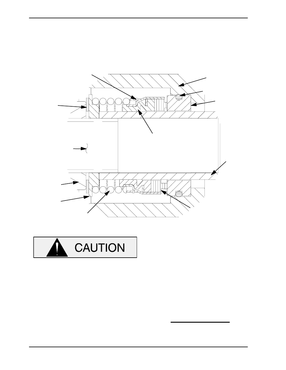
ENGINE
CRANKSHAFT
O-RING
IMPELLER
IMPELLER
SHIMS
SHAFT
SLEEVE
STATIONARY
SEAT
ROTATING
ELEMENT
SPRING
INTERMEDIATE
SPRING
SEAT
BELLOWS
RETAINER
Figure 3. 25271−043 Seal Assembly
This seal is not designed for operation at
temperatures above 160
_F (71_C) Howev-
er most petroleum products such as gaso-
line are more efficiently handled at ambient
temperatures. Do not use at higher operat-
ing temperatures.
If the intermediate (7) was removed, lay it on a flat
surface with the impeller side facing up.
Subassemble the O-ring onto the stationary seat,
and press this subassembly into the intermediate
bore until it seats squarely against the shoulder.
Slide the assembled intermediate and stationary
seat over the shaft and secure the intermediate to
the engine bellhousing with the hardware (13 and
14). When installing the intermediate, use caution
not to damage the stationary seat on the shaft
threads.
NOTE
If the intermediate was not separated from the en-
gine during disassembly, subassemble the O-ring
into the stationary seat, and use a piece of plastic
pipe to press the seat into the intermediate bore un-
til fully seated. The O.D. of the pipe should be ap-
proximately the same as the O.D. of the seal spring.
Subassemble the rotating element into the retainer
and bellows, then slide this subassembly onto the
shaft sleeve (10) until the face of the rotating ele-