A. unpacking, B. amplifier panel tour – NXG Technology NX-PROSUB125/NX-PROSUB300 User Manual
Page 3
3
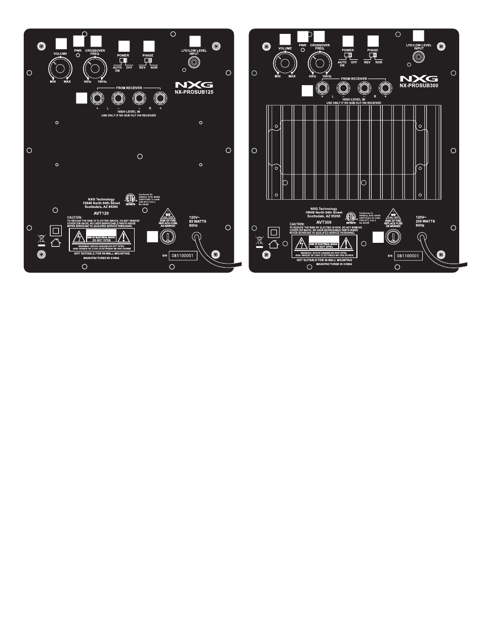
FIG. 1A - NX-PROSUB125 rear panel
FIG. 1B - NX-PROSUB300 rear panel
A. UNPACKING
Remove the NX-PROSUB125/NX-PROSUB300 from its packing
carefully and inspect it for any shipping damage. If you discover
damage, contact your NXG dealer or installer immediately.
If possible, save the carton and internal packing. It’s the best
possible protection for your NX-PROSUB125/NX-PROSUB300 if
you need to move it or return it for service.
Keep your sales receipt in a secure place. It helps establish the
duration of your warranty and is good for insurance purposes (just
in case anything happens to your stereo/home theater system).
B. AMPLIFIER PANEL TOUR
As a starting point, set the control around 80 Hz. if you are using
left and right tower speakers, 100 Hz. with bookshelf speakers, and
120 Hz. with small mini-speakers.
4. POWER/AUTO ON SWITCH. This slide switch turns the
NX-PROSUB125/NX-PROSUB300 on and off. When this switch is
in the AUTO ON position, the amplifier will stay turned on as long
as a signal is being fed to the subwoofer amplifier. 15 to 20 min-
utes after you stop playing music or a video, the amplifier goes into
STANDBY mode – see (2). When you again begin to play music or
a video, the amplifier will automatically turn on.
5. PHASE SWITCH. This switch is used to set the subwoofer’s
phase to either normal “0
°” or reverse “180°” (out of) phase. Once
you determine the placement of the NX-PROSUB125/NX-PRO-
SUB300, you will need to try both positions of this switch for the best
bass output for your listening position. The physical location of your
subwoofer and main speakers determines the phase setting that will
sound best at your main listening position. If this requires using the
“180
°” mode, don’t worry, there is nothing “abnormal” about it.
6. LFE/LOW LEVEL IN. This connection is used ONLY if you have a
Dolby Pro Logic or Dolby Digital receiver/integrated amplifier
which has a subwoofer output.
7. FROM RECEIVER HIGH LEVEL IN. Connects to your receiver’s
speaker terminals. These color-coded connectors are used to hook
the NX-PROSUB125/NX-PROSUB300 to your receiver if it does not
have sub- woofer out or LFE output connections. This is explained
in item 6 above.
8. REMOVABLE FUSE HOLDER. By pushing in and turning counter-
clockwise, you can remove and replace the fuse. Check the rating
on the fuse for proper size of your unit.
Before actual hookup, you should familiarize yourself with the con-
nections on the back of the NX-PROSUB125/NX-PROSUB300, as
shown in Figs. 1A and 1B above.
1. VOLUME CONTROL. Rotating this knob clockwise increases
the output level of the subwoofer. To start out, make sure that the
VOLUME is turned all the way down (fully counterclockwise).
Later, after some initial listening tests, you can adjust the volume
to your own tastes. However, care should be taken not to overdrive
the subwoofer to the point of audible distortion.
2. POWER INDICATOR. When the amplifier is ON, this indicator
will be green. When the amplifier is in the OFF or STANDBY mode,
the indicator is off.
3. CROSSOVER FREQUENCY CONTROL. This control determines
what lower part of the frequency spectrum will be reproduced by
the NX-PROSUB125/NX-PROSUB300. It is a “crossover” control.
Rotating the knob sets the point where all lower frequencies will be
handled by the subwoofer.
1
2
3
4
5
6
7
8
1
2
3
4
5
6
7
8