New construction – NXG Technology NX-Si8522 User Manual
Page 3
NXG recommends the use of a minimum of 16-gauge wire. For wire options consult your retailer or custom audio contractor.
1. NXG Signature Series Speakers are designed to be installed in the wall or ceiling area between studs. Using a stud finder, make sure you
are between two studs. Using the supplied template, trace around the outside with a pencil.
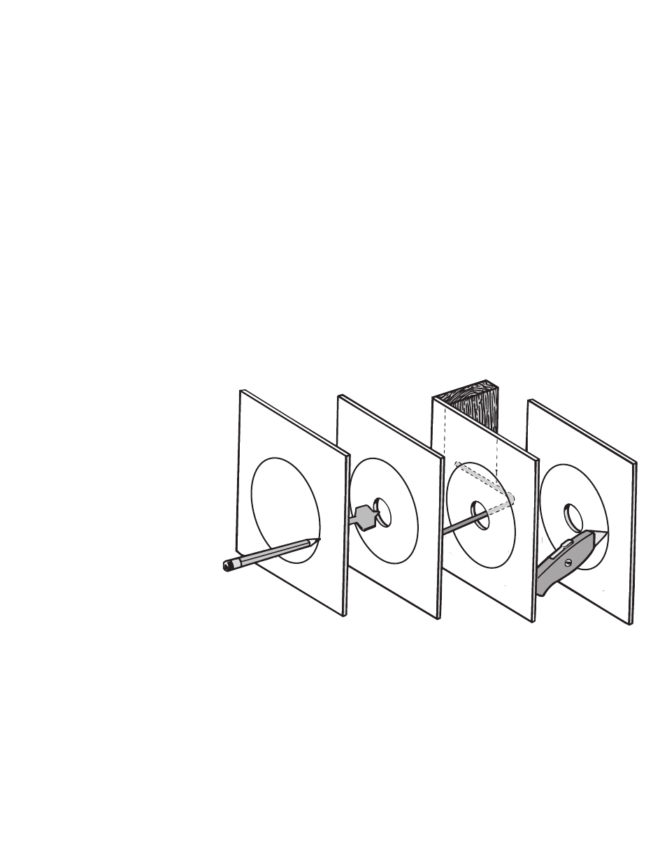
2. Cut the hole using your drywall saw. You may want to start with a small hole in the center of the outline. This will allow you to check for
any obstructions that may exist behind the desired location. CAUTION: Be certain electrical wiring, water pipes or heating ducts do not
interfere in the planned installation areas prior to drilling or cutting the wall. See Fig. 3.
3. Run speaker wire from your amplifier, volume control or speaker switching device to the speaker location.
4. Carefully remove the grille and inner grille backing. (Note: The open cell foam inner grille backing is designed to hide speaker components
from view and may be removed if desired.) If you like the standard white finish of your NXG speakers, skip to step 5, but if if you want your
speakers to blend in with a colored wall or ceiling, now is the time to paint your speaker’s outer frame and perforated grille. (Remove the
foam inner grille backing and put it aside in a clean and dust free area for later reinstallation if desired.) The speaker’s outer surface will accept
ordinary latex wall paint or aerosol spray paint. Because the speaker baffle surface behind the grille should remain unpainted, you will need to
cover this area with the supplied paint mask. Cover the speaker’s interior black surface, woofer and tweeters. Paint the outer speaker frame and
grille separately. (Grille painting hint: Use a paint roller that is nearly out of paint to first paint the inside of the grille, then the outside. This will
avoid paint filling the grille perforations.)
Speaker Installation In Existing Construction (Fig. 3)
Once you have selected the location for your speakers, you are ready to install them. You will need the following:
• Stud Finder
• Drill & Drill Bits
• Wire Cutter/Strippers
• Pencil
• Utility Knife or Drywall Saw
• Small Level
• Masking Tape
• Phillips Screwdriver
• Speaker Wire
FIG. 3
5. Attach the wires to the input terminals
(right and left) on the rear of the speaker
for stereo operation and set the switch in
Fig. 4B to the “8 ohm” mode. For single
channel operation you can attach one
set of wires to either set of input con-
nectors and set the switch in Fig. 4A to
the “4 ohm” mode. Remember to main-
tain proper polarity with the amplifier by
attaching the positive (+) lead to the red
terminal and the negative (-) lead to the
black terminal.
6. See Figs. 4A and 4B on reverse.
With the speaker wire(s) attached to the
speaker, slide the speaker up inside the
cut-out hole. Center the speaker in the
cut-out hole and turn the four locking
screws clockwise until the speaker is
drawn up snugly to the wall board from
behind, clamping the speaker in place.
Try to tighten each screw equally.
Replace the speaker grill by gently
pressing it into place.
New Construction
1. Determine speaker location and mark it on your plans for future reference.
2. If possible, run speaker wires after HVAC and electrical wiring is in place.
3. Secure speaker wires in place along the run with insulated staples only and be careful not to pierce the wire’s insulation. Allow a bit of
slack for expansion of building materials.
4. Needless to say, the actual speaker should not be installed until the wall board is in place. In the meantime, leave several feet of wire
coiled up and secured at the back side of the mounting hole.
5. To complete the installation follow steps 2 through 6 above.
(Continued on reverse)