Set-up features – Ultimate Support TOUR-Series User Manual
Page 2
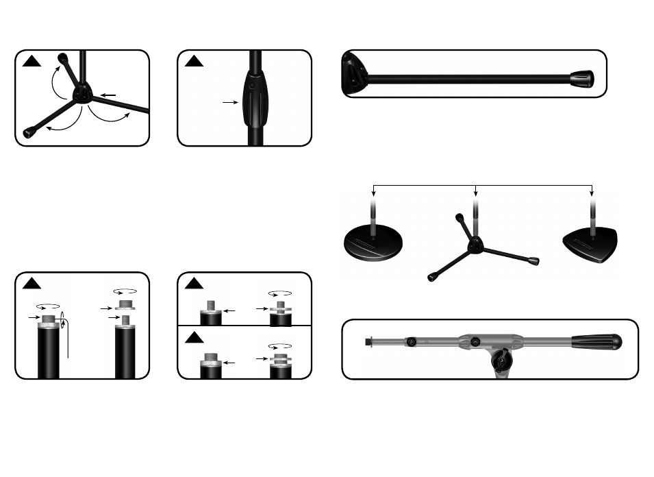
STEP 2
Turn the ergonomic Patented Quarter-
Turn Clutch counter clockwise a quarter
turn. Adjust stand height up or down.
Securely retighten clutch by turning
clockwise.
STEP 1
Tripod Base: Fold out legs until they
are fully extended. No tightening of
nobs is necessary.
Weighted Base: Shaft screws into
weighted base.
Modular Base Design: Allows any
Tour shaft to be used with any Tour
base, tripod or weighted.
2
3
LEG REPLACEMENT
The legs on the Tour and Pro Series Mic Stands are built to be extra durable, withstanding
the rigors of everyday use. However, if a leg should get damaged, the stand is designed to be
fi eld repairable and the legs can be replaced. Please visit www.ultimatesupport.com or call
customer support at 800-525-5628 for more details.
STAND & BOOM PACKAGE MODELS:
TOUR-T-T, TOUR-T-TALL-T, TOUR-T-SHORT-T, TOUR-RB-SHORT-T
The “Ulti-boom” telescoping mic boom features an oversized “rotation hub” - the place
on a boom where everything comes together. Ultimate Support’s center hub is the largest
on the market, increasing friction, and reducing any chance of slipping. Adjust it once and
forget about it!
STEP 3
Universal Mic Attachment
To adjust US to metric, use tool provided or
1.5 Allen Wrench to unlock threads. Turn
US threads counter clockwise until it is
removed. US MIC-Lock will come off too.
STEP 4
Universal Mic Attachment
After choosing desired thread, place
microphone on universal mic attachment.
Then turn MIC-Lock counter clockwise to
lock mic in place.
set-up
features
Ergonomic knobs
Ergonomic knobs
Universal Mic
Attachment
Heavy-duty
Counter-weight
Oversized
Rotation Hub
1
2
Ergonomic
Patented
Quarter-Turn
Clutch
Same Tour Mic Shaft
Legs Lock
in Place
Metric
US
4
4
MIC-Lock
LOCKED
LOCKED
MIC-Lock
THE SHAFT OF ANY TOUR STAND CAN BE USED WITH ANY TOUR BASE!
Metric
US Mic Lock
Mic T
ool
or
1.5 Allen Wrench
US
3