Ultimate Support MS-80B User Manual
Page 2
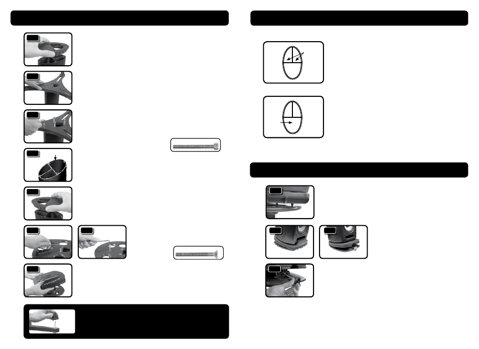
1. Place rubber coupler on aluminum column.
When placed properly, the larger weight
channel will be covered and the two cable
channels will be visible.
2. With the feet caps facing up, set bottom
base on top of rubber coupler. When set
properly, the larger weight channel will
be completely covered and the two cable
channels will still be visible.
3. Hand tighten the four socket head cap
screws in base. Use provided 5mm allen
wrench to finish tightening socket head
cap screws.
4. Turn column upside right. (If desired, add
sand or shot to the larger weight channel
at this point.)
5. Place second rubber coupler on the top
aluminum column. When placed properly,
the larger weight channel will be covered
and the two cable channels will be visible.
6. Set top base on column w/cable channels
still visible. Tighten the four countersink
screws in base using provided 4mm
allen wrench.
7. MS-100 ONLY: Place adjustable monitor
platform on top base, making sure feet
spikes are securely set in indented holes
before placing studio monitors on top of
stand.
Column Assembly (MS-100 and MS-90)
Adjustable Platform Setup (MS-100 and MS-80)
Column Channels (MS-100 and MS-90)
2
3
1. AXIS ADJUSTMENT (MS-100): Instead
of moving the entire stand, you can
adjust the axis of the platform by moving
it in a circular motion clockwise or
counterclockwise until reaching the
desire position. NOTE: Be sure all four
spikes are securely seated in indented
holes on base before placing studio
monitors on top of stand.
2. ANGLE UP OR DOWN: Your studio
monitors can angle up (2.1) or down
(2.2) depending on your situation.
Please choose and set before final
angle adjustment.
3. ANGLE ADJUSTMENT: Turn knob
clockwise or counter clockwise for
precise angle adjustment.
Top View of Column
Cable
Channels
1
3
2
3
5
MS-100
7
MS-100
MS-90
6
6
MS-100
1
Top View of Column
Weight
Channel
The column of the MS-100 and MS-90 all feature three channels.
Two of the channels are used for cables while the third, larger
channel is for filling with sand or shot.
It is best to keep audio and power cables separate from each
other, so run your audio cable down one channel and your power
cable down the other.
Fill the weight channel with sand or shot after point 4 in the
COLUMN ASSEMBLY section of instructions (see left). This weight
adds mass and eliminates sonic resonance.
Socket Head Cap Screw
Countersink Screw
2.1
2.2
Angle Down
Angle Up
4
Weight Channels
FOOTCAPS:Leaverubberfootcapsonforplacementonhard
woodfloorsorothersuchsurfaces.Takethemoffanduse
spikesforsettingoncarpet.