Iv. alarm status, V. wiring diagram, Specifications – Spencer Bearing Temperature Monitor Control User Manual
Page 3
The Spencer Turbine Company
600 Day Hill Road Windsor, CT 06095-4706
TEL 800-232-4321
◆
860-688-8361
◆
FAX 860-688-0098
3
IV. Alarm Status
The BTMC has two tiers of fail safe alarm
monitoring (the relay is energized in normal
operation and de-energized on alarm). The
first tier is a Warning. When the bearing
temperature is 3 percent below the Alarm
set point, the corresponding alarm LED,
Inboard (2) or Outboard (5), will flash. The
flashing LED is a visual indicator that the
bearing temperature is close to the shut-
down set point and precautionary measures
should be taken. A common "Warning"
relay (K3) will also be de-energized on
alarm. The form "C" contact may be
used for remote indication of a "Warning"
condition.
The second tier is an Alarm (Shutdown). In
the Alarm state, the alarm LED, Inboard
(2) or Outboard (5), will illuminate in a
steady state when the bearing temperature
exceeds the set point. The corresponding
relay output will then shut down the blower
or vacuum producer (K1 = inboard, K2 =
outboard). The relay output may also be
used for remote indication of shutdown.
To clear any Warning or Alarm, the
Reset/Enter "R/E" button (8) must be
pressed for 5 seconds. If the bearing
temperature still meets or exceeds the
warning or alarm levels, the controller
cannot be reset. The bearing must be
cooled to an acceptable level before the
blower or vacuum producer will be allowed
to start up again.
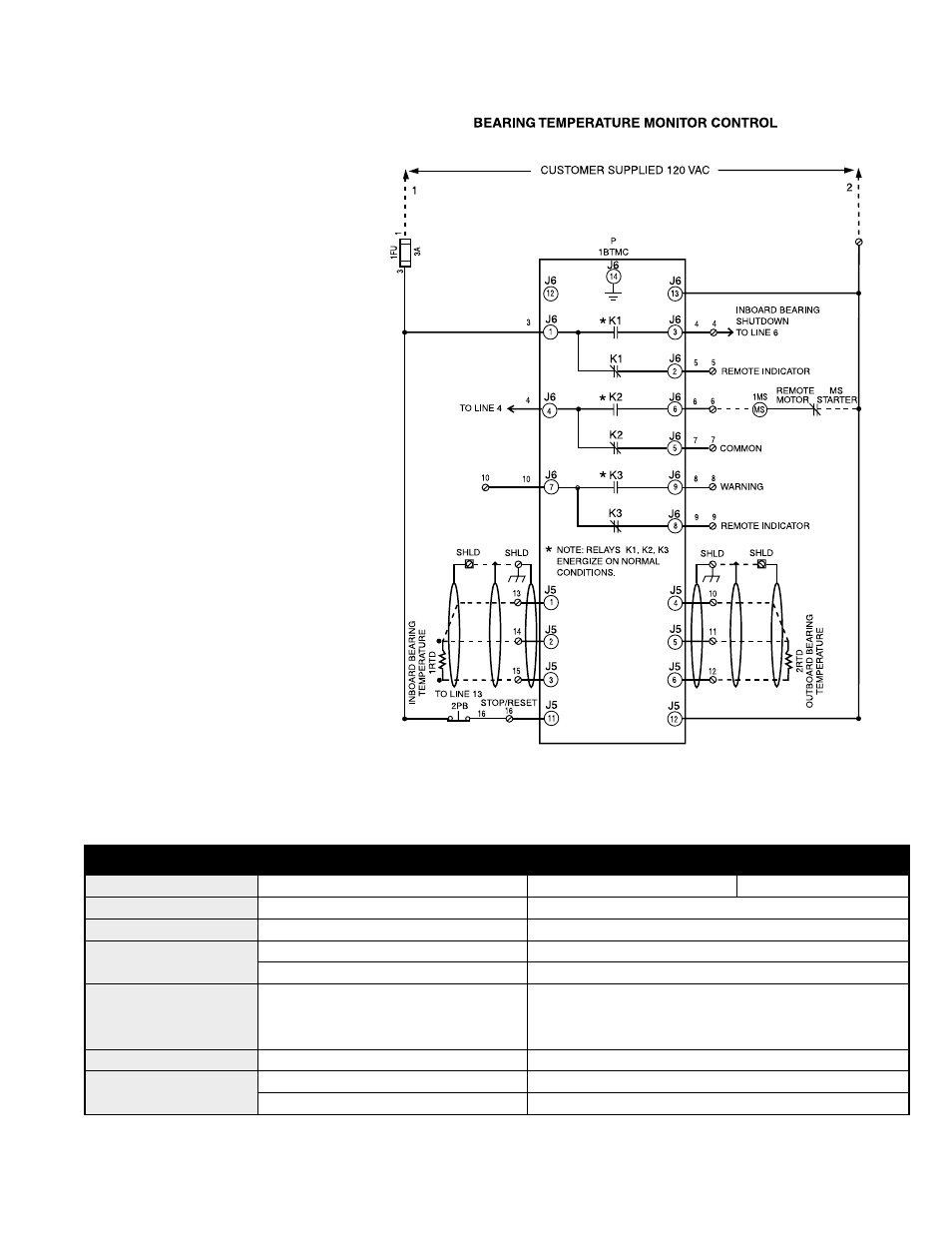
V. Wiring Diagram
Specifications
Dimensions (H x W x D)
Overall 5
1
/
8
x 6
1
/
8
x 3
Cutout 4
3
/
4
x 5
3
/
4
x (n/a)
Part Number CTB 90009
Digital Display
7 Segment / LED
5
/
8
High
Display Inboard/Outboard Bearing Temperature
Power Supply
120/240 VAC, 1Ø, 50/60 Hz
Inputs
Analog (2)
100
Ω
platinum RTD
Digital (1)
120 VAC (Reset)
Outputs
(3) Provided Rated @: 5 A General
Inboard Shutdown,
Purpose, 250 VAC;
1
/
6
HP 120 VAC,
Outboard Shutdown,
2A Pilot Duty, 120 VAC
Common Warning Alarm
Nema Ratings
1, 2, 12, 4, 4X
Note: N-12, 4 and 4X, Indoor Only
Agency Approvals
UL 873
File #E151368, 97ME50259, DD/215K
CUL
CAN/CSA 22.2, No. 24-93
Note: Dotted lines indicate field wiring.