Si 3ct lp, Ceiling speaker user’s guide – Extron Electronics SI 3CT LP User Guide User Manual
Page 2
SI 3CT LP
Ceiling Speaker
User’s Guide
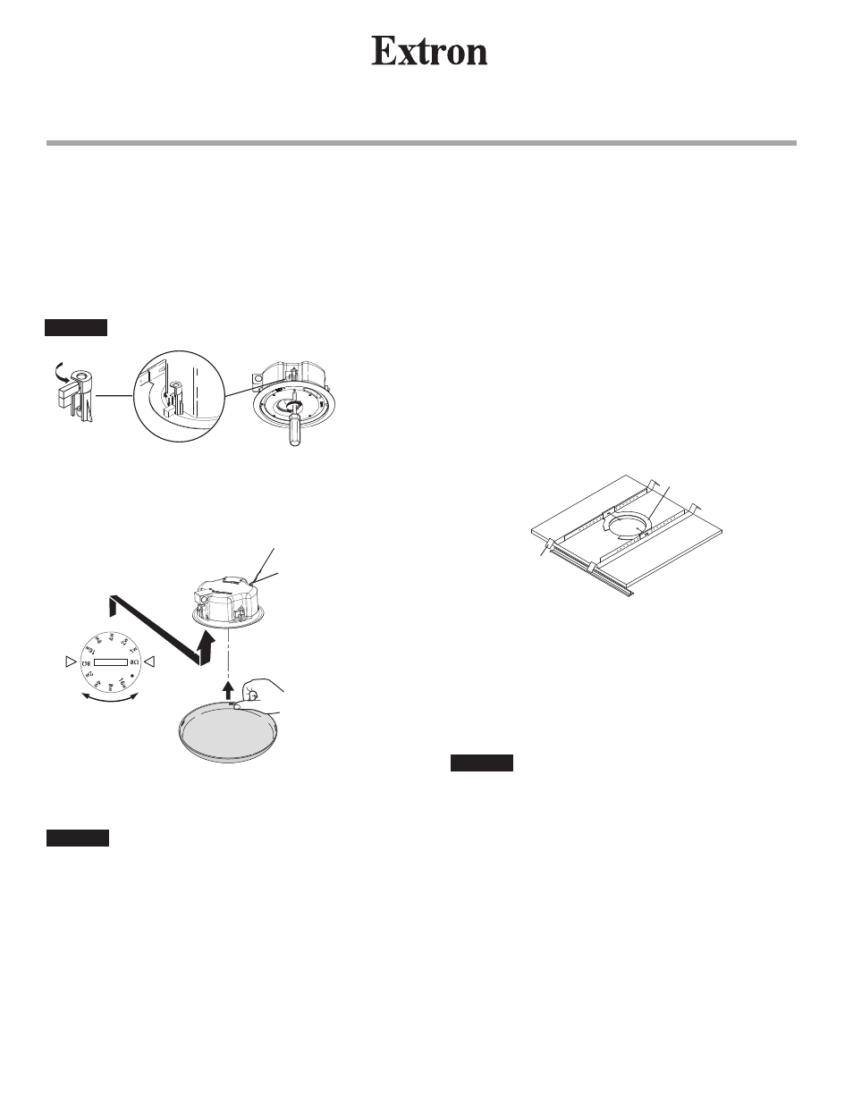
5
Connect a secondary support line from the seismic tab to a
secure support point, as shown below.
Set the rotary tap selector (shown above) to the proper
position.
CAUTION
Do not turn the tap selector to the
8
Ω
position
when using 70 V / 100 V lines.
Install the speaker grille.
2
4
Loosen the four screws on the front baffle (counter
clockwise) 1/2 turn. Insert the speaker in the ceiling hole,
then tighten the screws (clockwise) until the dog legs clamp
the speaker to the ceiling. See the following illustration.
Do not overtighten screws.
CAUTION
Remove the ceiling tile where the speaker is to be installed.
Loosen the four screws on the front baffle (counter
clockwise) 1/2 turn. Then tighten the screws (clockwise)
until the dog legs clamp the speaker to the ceiling.
1
Cut the hole in the tile (see step
1 on page 1).
2
8
Set the rotary tap selector and install the grille (see step
5 of
Frame Construction Ceiling Installation on this page).
5
Connect the wires to the speaker terminal connector (see
step
3 on page 1).
3
Bring the speaker cable through the hole of the cut tile,
then reinstall the tile.
4
Remove the adjacent tile. Place 2 V-rails and 1 C-ring
across the tile where speaker is to be installed. Bring the
speaker up to the bottom of the hole in the ceiling tile.
6
Do not overtighten screws.
CAUTION
7
Connect a secondary support line from the seismic tab to
a secure support point (see step
5 of Frame Construction
Ceiling Installation on this page).
V-rail
C-ring
Suspended Ceiling Installation
Frame Construction Ceiling Installation,
cont’d
Apply 4 pieces of
black putty (supplied),
equally spaced 90° apart,
to the upper inside edge
of the grille.
Seismic Tab &
Support Line
Adjusting the Tap Selector
.
70 Volt
100 Volt