Step 1 - float removal and replacement, Caution – Xylem MM 715B Series 63 64/764 and 65/165 Replacement Floats User Manual
Page 2
OFF
ON
2
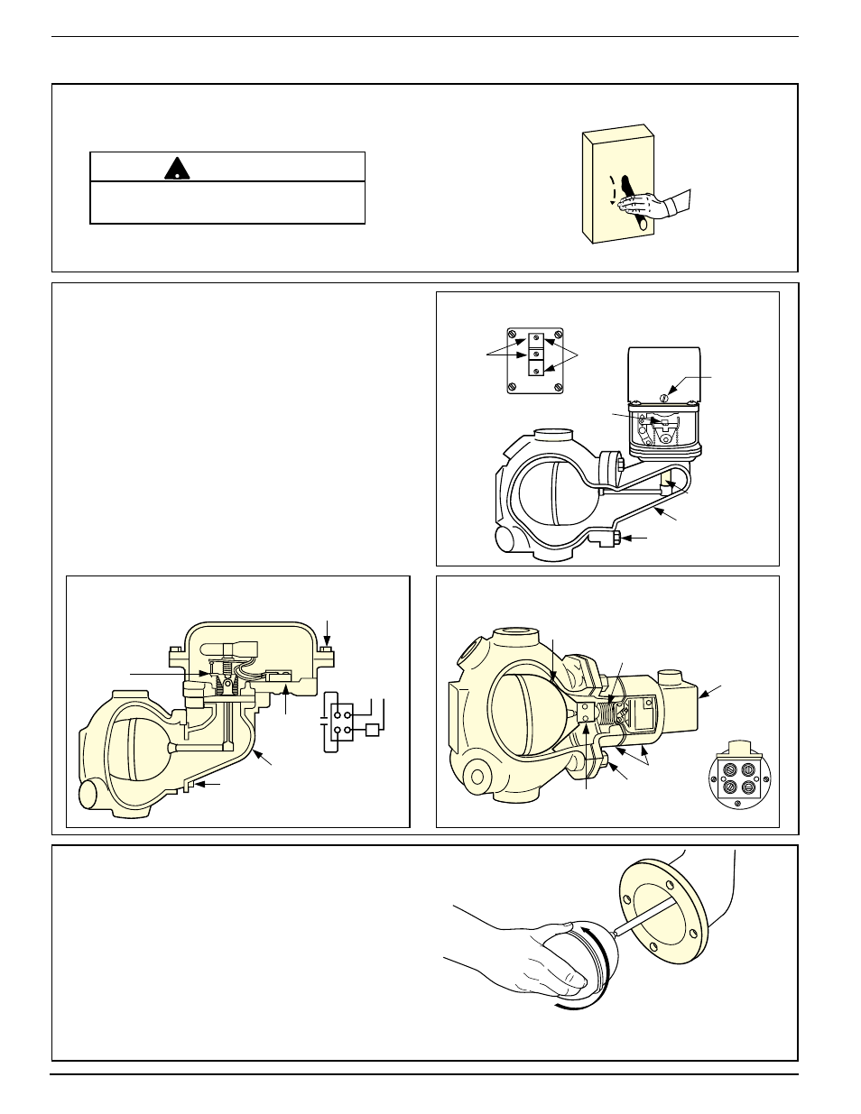
STEP 1 - Float Removal and Replacement
a. Turn power off to boiler and all controls.
Allow boiler to cool to 80˚F (27˚C) and
reduce the pressure to 0 psi (0 bar).
Drain water in the boiler to a level that is
below the float chamber.
b. Remove Head Assembly
• Remove screws (
A) and lift off
switch cover.
• Identify
terminal connections for
rewiring and then disconnect all wires
from
terminal panels.
• Remove head bolts. Carefully remove
head assembly from control body.
• Carefully place
head assembly in vice
where replacement work can be
performed more conveniently.
c. Remove and Replace Float
• While securely holding the
arm or mounting
block, where indicated in the diagram
above, unscrew
float ball from the assembly
Holding the arm or mounting block reduces
the risk of damaging the bellows from
unnatural stresses.
• Screw new float onto assembly.
On model 64 units, be sure the float stop
bracket is in proper position.
There may be more than one source of
power to the boiler.
!
CAUTION
SECURE THE FLOAT
ARM HERE
COVER
BOLTS (A)
LINE
TERMINAL
PANEL
HEAD ASSEMBLY
HEAD BOLTS
LOAD
C.
N.
N. C.
O.
LOW
WATER
ALARM
TERMINALS
LOW
WATER
CUT-OFF
TERMINALS
HEX HEAD BOLTS
HEAD ASSEMBLY
FLOAT ARM
SWITCH COVER
SCREW
(A)
TERMINAL PANEL
SECURE THE
FLOAT ARM HERE
FLOAT STOP
BRACKET
BELLOWS
SECURE
FLOAT MOUNTING BLOCK
HERE
HEX HEAD BOLTS
SWITCH COVER
TERMINAL PANEL
HEAD ASSEMBLY
1
TOP
2
3
4
MODEL 63-HD
MODEL 64-HD
MODEL 65-HD/165-HD