Mcdonnell & miller, Maintenance, Step 4 - switch adjustment – Xylem MM 704B No. 2 Switch For series 47, 247, 63, 51, and 53 water feeders to add the low water cut-off function User Manual
Page 3
MAINTENANCE:
• Replace the switch every 10 years or when the components do not operate properly. More frequent
replacement may be required when severe conditions exists.
The control and switch have been factory adjusted and should not need any further adjustment in the field.
Observe the devices being activated by the control and switch and, should adjustment be needed, follow
the following steps.
STEP 4 - Switch Adjustment
L
M
a. Using a flat head screwdriver and 5/16” nut
driver, loosen adjusting screw (M) until cam
is set in lowest position.
b. Slowly, turn adjusting screw (M) raising the
cam until the switch clicks, opening the
common and normally closed contacts. Hold
adjusting screw (M) in position and tighten
nut (L) using 5/16” nut driver on the opposite
end.
c. Observe the devices being activated by the switch
and control to determine if the switch is activating
when desired.
If further adjustment is required, repeat Step c.
ITT
8200 N. Austin Ave.
Morton Grove, IL 60053
tel: 847-966-3700
fax: 847-966-9052
www.mcdonnellmiller.com
McDonnell & Miller
©2008 ITT Corporation
Printed in U.S.A. 12-08 210529
3
Neutral
120 V.A.C.
Supply Hot
Used as a Mainline Switch�
and/or Low Water Alarm
FIGURE 1
Used as a Pilot Switch to Coil�
of Relay or Motor Starter
Low
Water
Alarm
Load
Load
Line
C.
N.C.
N. O.
C.
N.C.
N. O.
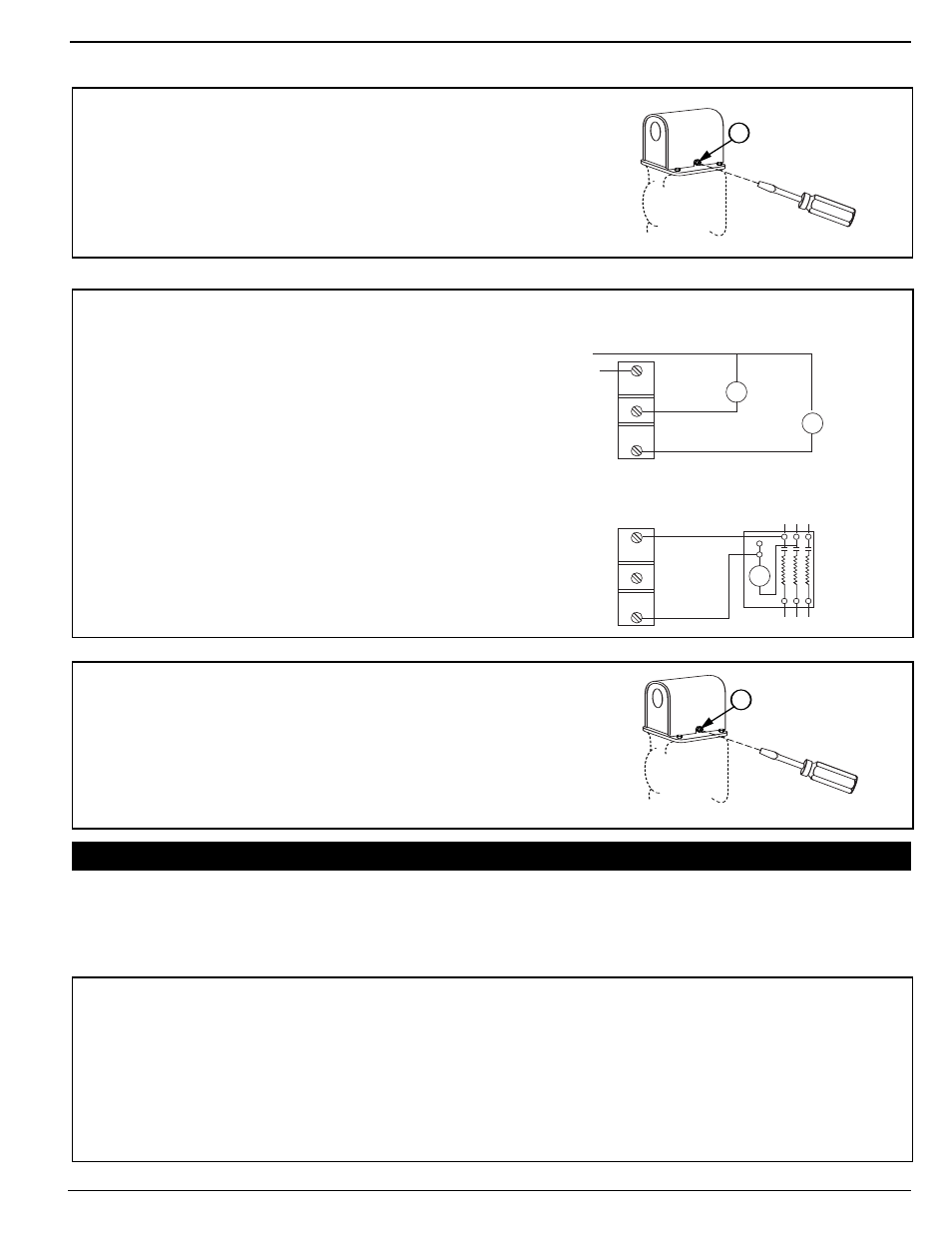
b. Using copper wire only, follow the wiring
diagrams in Figure 1 to wire the No. 2
Switch. Terminals C and NC are the low
water cut-off switch. Terminals C and NO
are the alarm switch. If the electrical load
exceeds the rating of the switch, use an
auxiliary relay or motor starter.
E
c. Slide the switch housing (E) onto the
switch and, using a flathead screwdriver,
tighten the two (2) screws that secure the
switch housing.
a. Check to see that the burner turns on and
off, by raising and lowering the water level
in the boiler.
b. Make sure there is travel in the float arm
after the burner goes on and off.
c. Repeat test several times.
E
a. Using the flathead screwdriver, remove the
two (2) screws that secure the switch housing (E).
STEP 2 - Electrical Wiring
STEP 3 - Testing
INSTALLATION COMPLETE