Flow rates, Installation, Step 1 - determine the location of the flow switch – Xylem MM 619F Series FS6 Flow Switch User Manual
Page 3
Pipe
Mode of Operation
Size NPT
Flow
No Flow
in. (mm)
Settings
gpm (lpm)
gpm (lpm)
3
⁄
4
(20)
Factory or
or
Minimum
.12
(.45)
.06
(.23)
1
(25)
Maximum
2.5
(9.46)
1.5 (5.68)
FLOW RATES
Settings will vary when used to sense flow of other
fluids.
3
NOTE: DO NOT USE LIQUID FLOW
SWITCHES ON SYSTEMS WITH
FLOW VELOCITY GREATER THAN
10 FEET (3M) PER SECOND.
Flow Rates
Values are ± 10%
Max. Flow
Rate gpm (lpm)
w/o Paddle
Damage
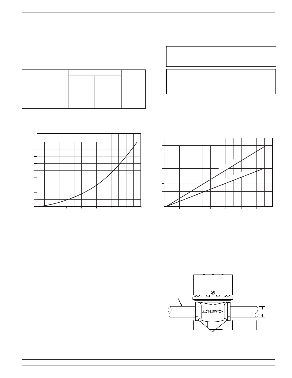
INSTALLATION –
STEP 1 - Determine the Location of the Flow Switch
5 x D
MINIMUM
5 x D
MINIMUM
D= PIPE DIAMETER
3/4
" or 1" PIPE
D
• The flow switch should be located in a horizontal
section of pipe where there is a straight horizontal
run of at least 5 pipe diameters on each side of the
flow switch.
• The flow switch must be installed in the upright
position as shown with arrow mark on side of casting
in the same direction as fluid will flow.
• Some system conditions that require more than 5
pipe diameters are high viscosity fluid and high fluid
velocity.
70 (265)
GPM CAPACITY
FS6 SERIES PRESSURE DROP
90
80
70
60
50
40
30
20
10
D
IF
F
E
R
E
N
T
IA
L
P
R
E
S
S
U
R
E
10
20
30
40
50
60
70
FS6 VELOCITIES IN FPS
40
30
20
10
VELOCITY IN FEET PER SECOND
GPM CAPACITY
10
20
30
40
50
60
70
FS
6-
3
/
4
"
PIPE
FS6
-1"
PIPE
NOTE: THIS PRODUCT IS NOT INTENDED
FOR USE IN POTABLE WATER
APPLICATIONS.
calculated using clean water in a horizontal pipe.
Flow rates required to activate the flow switch
are shown in chart below.These values were